Wiring rubber coating tool
A technology of encapsulation and tools, applied in the direction of connection, circuit/collector parts, electrical components, etc., can solve problems such as cable grounding, electric shock to personnel, and irregular packaging.
- Summary
- Abstract
- Description
- Claims
- Application Information
AI Technical Summary
Problems solved by technology
Method used
Image
Examples
Embodiment 1
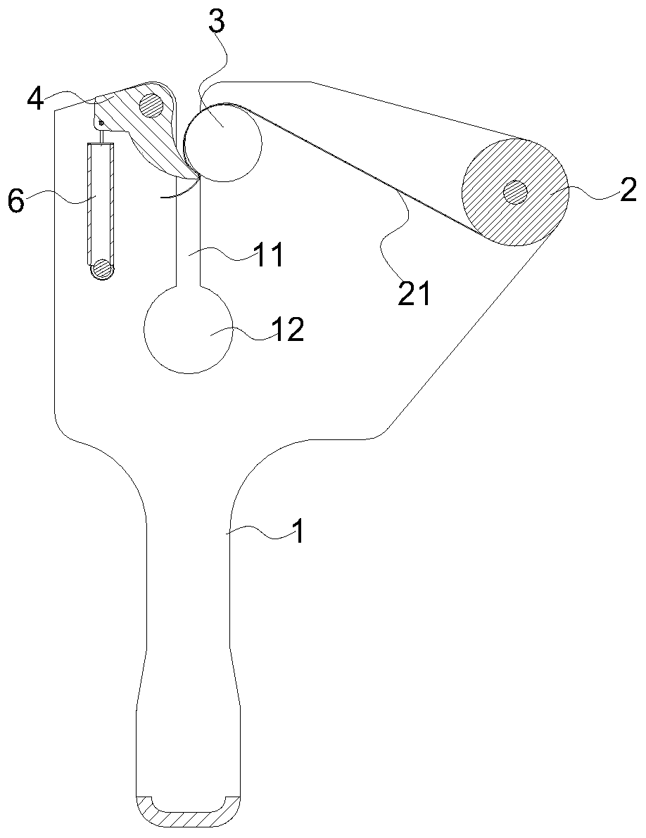
[0038] Please refer to figure 1 , the present embodiment provides a wiring encapsulation device, including a holding part 1, and the holding part 1 is provided with a bearing part, a guide part 3 and a rubber pressing part 4. An adhesive cloth roll 2 is placed on the supporting part, and the pressing part 4 is rotatably arranged relative to the holding part 1 , and the pressing part 4 is provided with a pressing part 41 . The guide 3 is provided with an arc portion, the arc portion is provided with a first contact point and a second contact point, the arc portion is in contact with the wire end of the wiring 5 at the first contact point, and the pressing portion 41 is pressed at the second contact point. The non-adhesive surface of the adhesive tape 21 is attached to the arc portion, and the first contact point and the second contact point are sequentially located on the feed path of the wire end of the wire 5 along the feed direction of the wire end of the wire 5 . One end o...
Embodiment 2
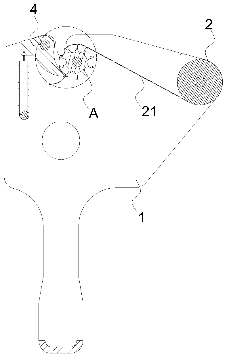
[0045] see Figure 2-4 , the main difference between this embodiment and the above-mentioned embodiment 1 is that in this embodiment, the guide member 3 is provided with a rotation point, the guide member 3 can rotate around the rotation point, and when the arc portion collides with the wire end of the wiring 5, it drives the guide Part 3 rotates to drive the adhesive tape roll 2 to continuously discharge the cloth, which is convenient for the adhesive tape roll 2 to discharge the cloth.
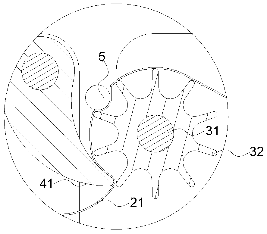
[0046] Specifically, in this embodiment, the guide member 3 includes a first rotating shaft 31 , and a circular ring is sleeved on the first rotating shaft 31 , and the circular ring can rotate around the first rotating shaft 31 .
[0047] And in order to keep the glued surface of the adhesive tape 21 on the wiring 5 and the guide 3 firmly bonded. Several protrusions 32 are evenly distributed along the circumferential direction of the ring on the outer wall of the ring. The adhesive tape 2...
Embodiment 3
[0050] Please refer to Figure 5 , the present embodiment provides a wiring lagging tool, which includes a holding part 1 , and a cutting mechanism is arranged on the holding part 1 , wherein the cutting mechanism includes a cutting part 7 , a fitting part 8 and a second reset part 9 . After the glue wrapping of the wiring head is completed, it is easy to understand that it is also necessary to cut and glue the excess tape on both sides of the thread head after wrapping. The traditional way adopts the working method of manual cutting and gluing, and the work efficiency is relatively low.
[0051] In this solution, the cutting part 7 is provided with a cutting part 71 and a contact part 72, the contact part 72 is provided with a third contact point 721 and a fourth contact point 722, and the cutting part 7 is provided with a second rotating shaft 74, The cutting element 7 can be relative to this second axis of rotation 74 . A clamping part is provided on the fitting part 8 , ...
PUM
 Abstract
Description
Claims
Application Information
 - R&D
- Intellectual Property
- Life Sciences
- Materials
- Tech Scout
- Unparalleled Data Quality
- Higher Quality Content
- 60% Fewer Hallucinations
Browse by: Latest US Patents, China's latest patents, Technical Efficacy Thesaurus, Application Domain, Technology Topic, Popular Technical Reports.
© 2025 PatSnap. All rights reserved.Legal|Privacy policy|Modern Slavery Act Transparency Statement|Sitemap|About US| Contact US: help@patsnap.com


