
Wire winding and rubber coating machine

A glue wrapping machine and wire winding technology, which is applied in coil manufacturing, electrical components, inductance/transformer/magnet manufacturing, etc., can solve problems such as low efficiency, low product yield rate, uneven skill proficiency of staff, etc., to achieve Effects of avoiding interference, ensuring accuracy, and improving accuracy

Pending Publication Date: 2022-04-08
SHENZHEN CITY POSONWONE TECH
View PDF1 Cites 0 Cited by
  • Summary
  • Abstract
  • Description
  • Claims
  • Application Information

AI Technical Summary

Problems solved by technology

However, the existing tube delivery mechanism is generally controlled entirely by the driving accuracy of the pipe transfer device in the tube delivery mechanism. Therefore, after a long period of use, the precision of the sleeve tube cutting length will become lower. One side of the wire passing assembly, and the upper and lower guide pins in the double guide pin assembly are arranged up and down, resulting in interference when the existing upper and lower guide pins move up and down, and the way of manually covering the tape On the one hand, the efficiency is low, and on the other hand, due to the uneven skill proficiency of the staff, the yield rate of the product is low

Method used


Image

  • Wire winding and rubber coating machine
  • Wire winding and rubber coating machine
  • Wire winding and rubber coating machine

Examples


Embodiment Construction

[0039] The following will clearly and completely describe the technical solutions in the embodiments of the present invention with reference to the accompanying drawings in the embodiments of the present invention. Obviously, the described embodiments are only part of the embodiments of the present invention, not all of them. Based on the embodiments of the present invention, all other embodiments obtained by persons of ordinary skill in the art without creative efforts fall within the protection scope of the present invention.

[0040]It should be noted that all directional indications (such as up, down, left, right, front, back, etc.) in the embodiments of the present invention are only used to explain each If the relative positional relationship, movement conditions, etc. between the components change, the directional indication will also change accordingly.

[0041] It should also be noted that when an element is referred to as being “fixed” or “disposed on” another elemen...


PUM


Abstract

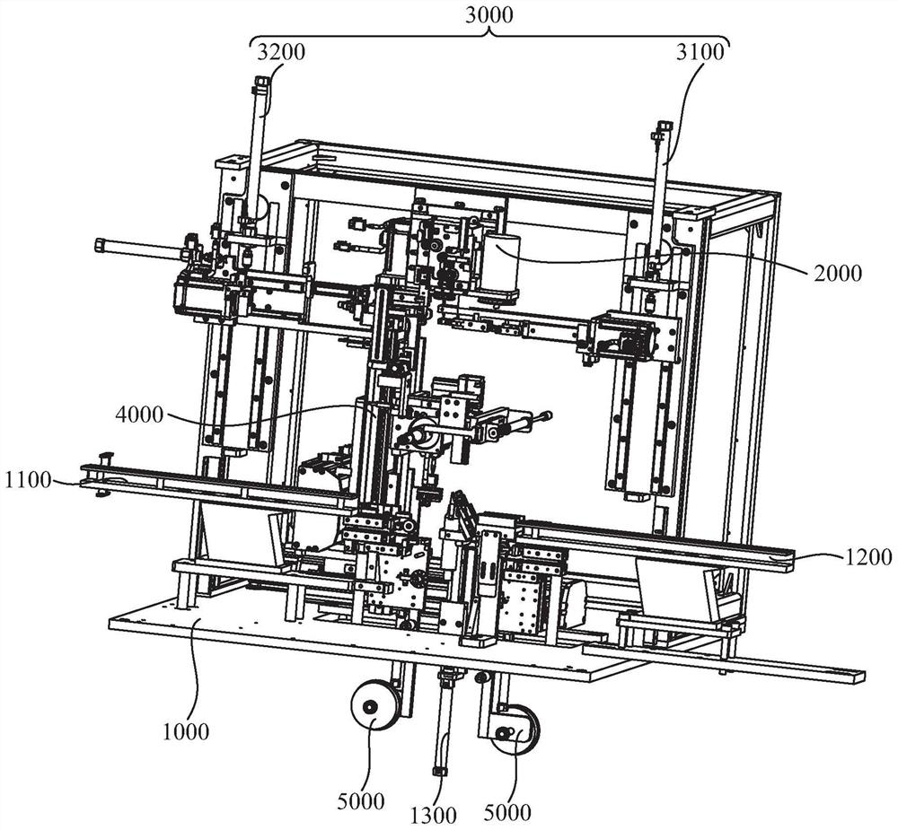
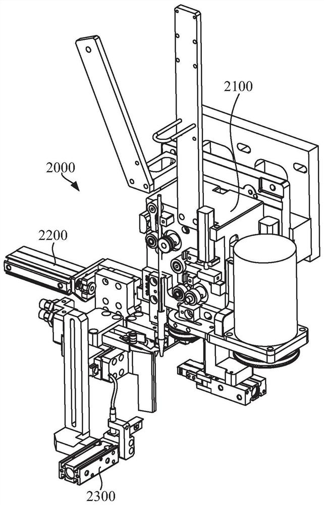
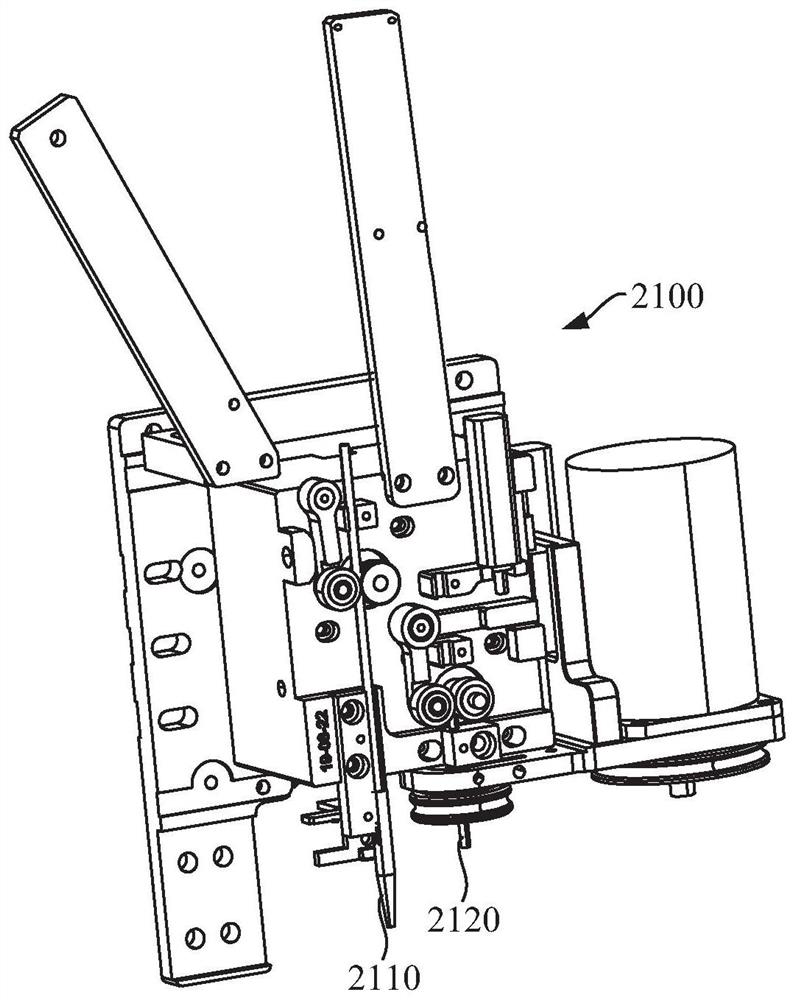
The invention discloses a wire winding and rubber coating machine, the wire winding and rubber coating machine comprises a rack, a wire outlet sleeve device, a wire leading device, a material clamping device and a rubber coating device, the wire outlet sleeve device comprises a wire pipe output mechanism, a sleeve cutting mechanism and a sleeve length detection mechanism, and the wire pipe output mechanism is provided with a sleeve output port and a wire output port; the casing pipe cutting mechanism comprises a pipe cutting assembly, a pipe clamping assembly and a first driving assembly, the pipe cutting assembly is used for cutting a casing pipe output from the casing pipe output port, the pipe clamping assembly is used for clamping the casing pipe, the first driving assembly drives the pipe clamping assembly to move, and the casing pipe length detection mechanism is used for detecting the length of the casing pipe output from the casing pipe output port; the wire leading device comprises an upper wire leading assembly and a lower wire leading assembly which are arranged around the peripheral side of the wire outlet sleeve device; and the rubber coating device is arranged on one side of the material clamping device. According to the invention, the cutting precision of the sleeve is improved, the situation of interference during movement of the upper lead assembly and the lower lead assembly is avoided, and automatic rubber coating is realized.

Description

technical field [0001] The invention relates to the technical field of winding equipment, in particular to a winding glue wrapping machine. Background technique [0002] Both transformers and inductors are electronic components made by winding coils on iron cores or magnetic cores. In the existing manufacturing process of transformers and inductors, wires are usually wound on iron cores or magnetic cores by winding machines. , and make the two ends of the guide electrically connected to the conductive posts on the iron core or magnetic core. [0003] In the existing Chinese patent with the publication number CN212676097U, the workpiece is clamped, and then the pipe outlet mechanism moves out the preset length of the sleeve and cuts it, so that the cut sleeve is conveniently set on the wire, and then passed through the double guide pin. The component leads out the wire to pass the wire on the component, so that the wire is wound on the workpiece through the rotation of the w...

Claims


Application Information

Patent Timeline
Patent Type & Authority Applications(China)
IPC IPC(8): H01F41/06H01F41/12H01F41/096B65H81/00
Inventor 李忠华麦荣建李海中王立军
Owner SHENZHEN CITY POSONWONE TECH
Learn More