
Front feeding device of bending machine

A bending machine and front-feeding technology, applied in the field of bending machines, can solve problems such as low efficiency, lack of feeding devices in bending machines, difficulty in ensuring continuous feeding of material plates, etc., and achieve the effect of fast and stable feeding

Inactive Publication Date: 2020-05-12
南京金球数控机床股份有限公司
View PDF0 Cites 1 Cited by
  • Summary
  • Abstract
  • Description
  • Claims
  • Application Information

AI Technical Summary

Problems solved by technology

[0002] The bending machine is a machine capable of bending thin plates. Its structure mainly includes a bracket, a workbench and a clamping plate. The workbench is placed on the bracket. The workbench is composed of a base and a pressure plate. The base is composed of a seat shell, a coil and a cover plate. The coil is placed in the depression of the seat shell, and the top of the depression is covered with a cover plate. However, the currently used bending machine lacks an effective feeding device, and the material is manually loaded in the factory. The efficiency is low, and it is difficult to ensure the continuous feeding of the material board

Method used


Image

  • Front feeding device of bending machine
  • Front feeding device of bending machine
  • Front feeding device of bending machine

Examples


Embodiment Construction

[0016] The following will clearly and completely describe the technical solutions in the embodiments of the present invention with reference to the accompanying drawings in the embodiments of the present invention. Obviously, the described embodiments are only some, not all, embodiments of the present invention. Based on the embodiments of the present invention, all other embodiments obtained by persons of ordinary skill in the art without making creative efforts belong to the protection scope of the present invention.

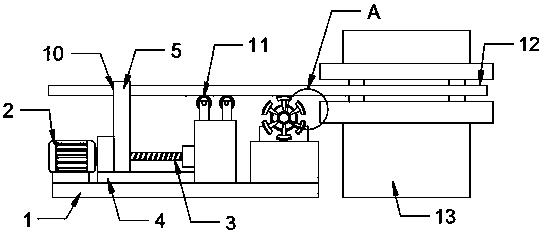
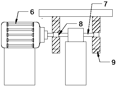
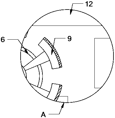
[0017] see Figure 1-3 , the present invention provides a technical solution: the front feeding device of the bending machine includes a base 1, the upper end side of the base 1 is fixedly provided with a first motor 2 through a mounting seat, and the output end of the first motor 2 is fixedly installed with Threaded rod 3, the upper end of the base 1 is fixedly provided with a chute 4 near the output end of the first motor 2, the upper end of the chute 4 is m...


PUM


Abstract

The invention discloses a front feeding device of a bending machine. The device comprises a base, one side of the upper end of the base is fixedly provided with a first motor through a mounting base,the output end of the first motor is fixedly provided with a threaded rod, the side, close to the output end of the first motor, of the upper end of the base is fixedly provided with a sliding groove,the upper end of the sliding groove is movably provided with a moving block, the upper end of the moving block is provided with a rectangular groove, the side, close to the threaded rod, of the upperend of the base is fixedly provided with a fixing block, four pulleys are fixedly arranged at four corners of the upper end of the fixing block respectively, a second motor is fixedly arranged at theside, far away from the first motor, of the upper end of the base through a mounting seat, a rotating shaft is fixedly arranged at the output end of the second motor, the outer end of the rotating shaft is sleeved with two feeding rods, and a plurality of feeding blocks are fixedly arranged at the outer ends of the two feeding rods. Rapid installation and feeding of material plates can be realized, and the problem that people make direct contact with the bending machine to cause harm is avoided.

Description

technical field [0001] The invention relates to the technical field of bending machines, in particular to a front feeding device of a bending machine. Background technique [0002] The bending machine is a machine capable of bending thin plates. Its structure mainly includes a bracket, a workbench and a clamping plate. The workbench is placed on the bracket. The workbench is composed of a base and a pressure plate. The base is composed of a seat shell, a coil and a cover plate. The coil is placed in the depression of the seat shell, and the top of the depression is covered with a cover plate. However, the currently used bending machine lacks an effective feeding device, and the material is manually loaded in the factory. The efficiency is low, and it is difficult to ensure the continuous feeding of the material board. Contents of the invention [0003] The object of the present invention is to provide a front feeding device of a bending machine to solve the problems raise...

Claims


Application Information

Patent Timeline
Patent Type & Authority Applications(China)
IPC IPC(8): B21D43/04
CPCB21D43/04
Inventor 刘平
Owner 南京金球数控机床股份有限公司
Learn More