Road garbage treatment equipment based on gear rotation
A technology for processing equipment and gears, which is used in grain processing, mechanical equipment, belts/chains/gears, etc., and can solve the problems of large road waste disposal, large volume occupation, and increased transportation costs.
- Summary
- Abstract
- Description
- Claims
- Application Information
AI Technical Summary
Problems solved by technology
Method used
Image
Examples
Embodiment 1
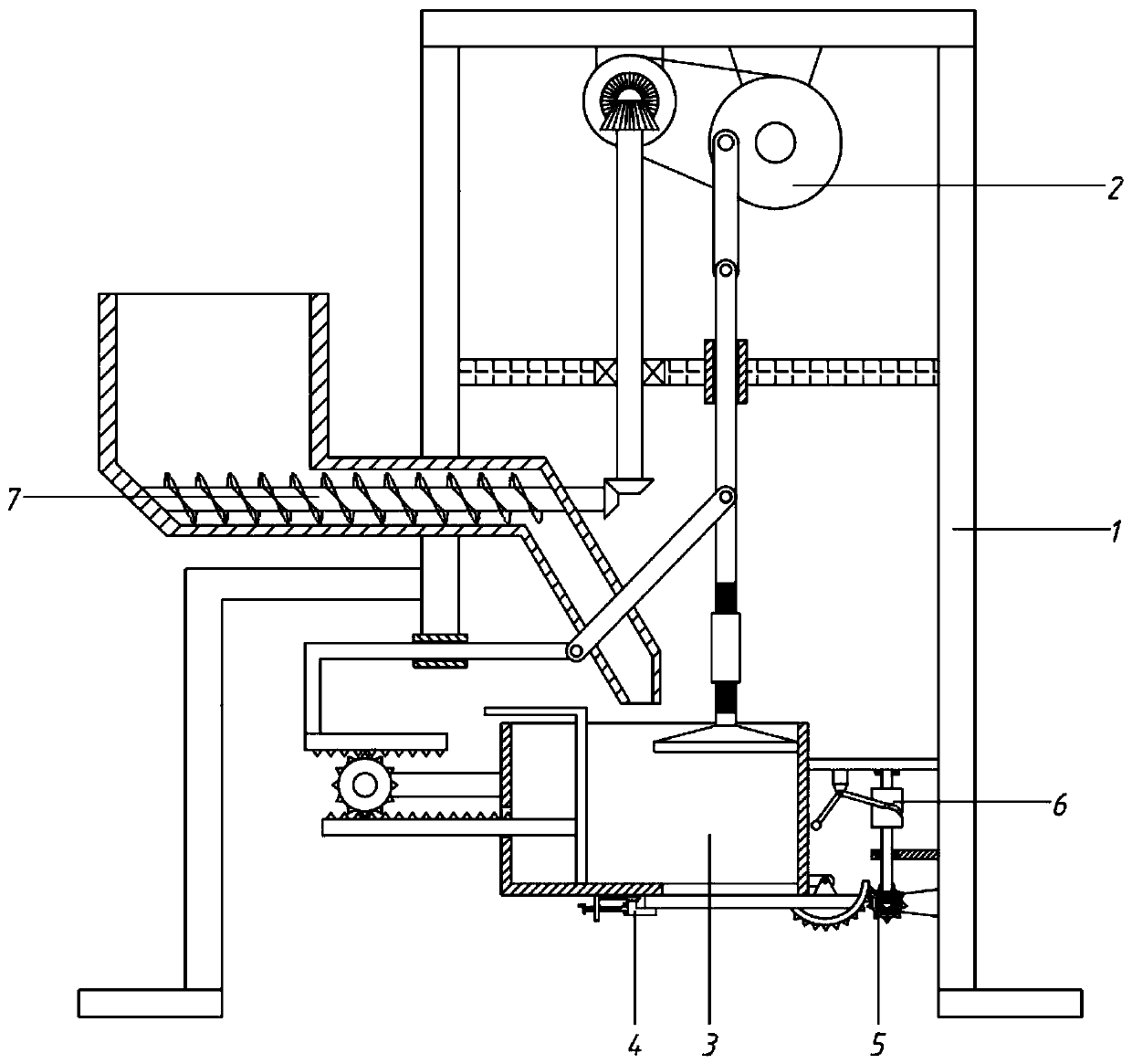
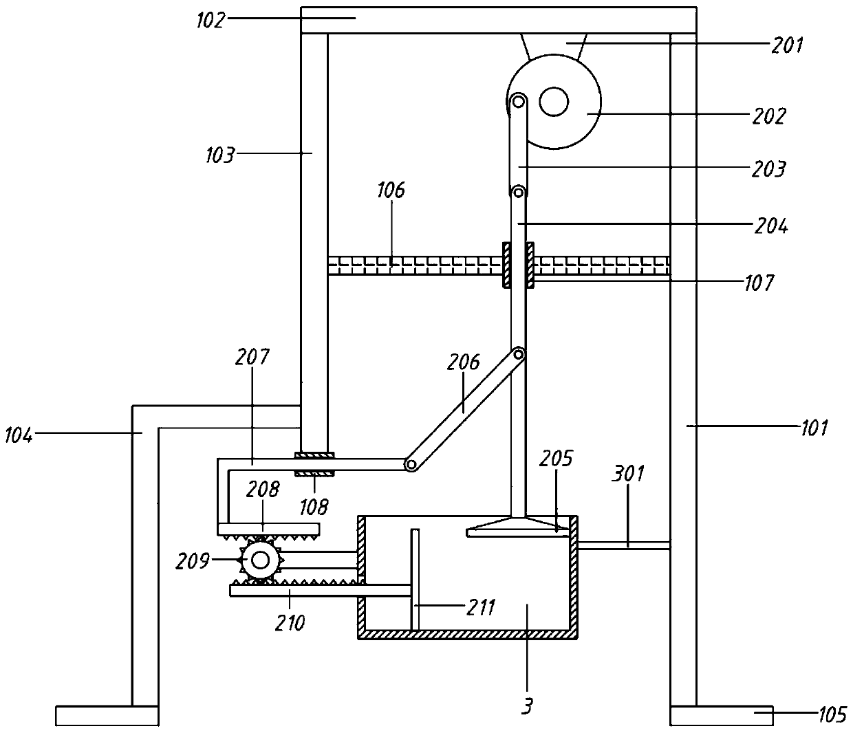
[0057] A processing device for road garbage based on gear rotation, including a bracket 1, a compression assembly 2 and a compression box 3;
[0058] The support 1 includes a right pole 101, a top plate 102, a left pole 103, a No. 1 inverted L-shaped bar 104, a leg 105 and a No. 1 support plate 106; The side is also connected with a No. 1 inverted L-shaped rod 104; the right end of the top plate 102 is connected downward with a right strut 101; the middle part of the left strut 103 and the right strut 101 are also connected with the No. The bottom end of the pole 101 is flush and connected to the right leg 105;
[0059] The lower part of the right pole 101 is connected to the compression box 3 through the fixed rod 301 to the left; the inner side of the bracket 1 is provided with a compression assembly 2, and the compression assembly 2 extends into the compression box 3 and compresses the road waste in the box.
Embodiment 2
[0061] A processing device for road garbage based on gear rotation, including a bracket 1, a compression assembly 2 and a compression box 3;
[0062] The support 1 includes a right pole 101, a top plate 102, a left pole 103, a No. 1 inverted L-shaped bar 104, a leg 105 and a No. 1 support plate 106; The side is also connected with a No. 1 inverted L-shaped rod 104; the right end of the top plate 102 is connected downward with a right strut 101; the middle part of the left strut 103 and the right strut 101 are also connected with the No. The bottom end of the pole 101 is flush and connected to the right leg 105;
[0063] The lower part of the right pole 101 is connected to the compression box 3 through the fixed rod 301 to the left; the inner side of the bracket 1 is provided with a compression assembly 2, and the compression assembly 2 extends into the compression box 3 and compresses the road waste in the box.
[0064] Wherein, the compression assembly 2 includes a No. 1 mot...
Embodiment 3
[0068] On the basis of embodiment 2,
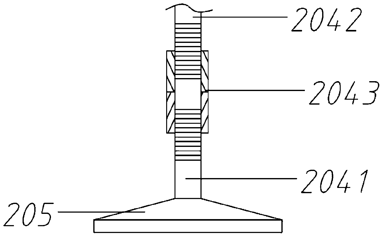
[0069] The bottom end of the second rod 204 is connected to the upper binder plate through an adjustment assembly; the adjustment assembly includes an upper threaded rod 2041, a lower threaded rod 2042 and an internal threaded pipe 2043;
[0070] The bottom section of No. 2 rod 204 is processed with threads to form the lower threaded rod 2042; the top of the upper binder plate 205 is connected with an upper threaded rod 2041, and the upper part of the upper threaded rod 2041 is processed with threads; The threaded rod 2042 is screwed; the helical direction of the upper and lower sections of the internally threaded pipe 2043 is opposite, so that when the internally threaded pipe 2043 rotates, the upper threaded rod 2041 and the lower threaded rod 2043 approach or move away synchronously, thereby compressing the upper binder plate 205 Adjust the intensity.
PUM
 Abstract
Description
Claims
Application Information
 - R&D
- Intellectual Property
- Life Sciences
- Materials
- Tech Scout
- Unparalleled Data Quality
- Higher Quality Content
- 60% Fewer Hallucinations
Browse by: Latest US Patents, China's latest patents, Technical Efficacy Thesaurus, Application Domain, Technology Topic, Popular Technical Reports.
© 2025 PatSnap. All rights reserved.Legal|Privacy policy|Modern Slavery Act Transparency Statement|Sitemap|About US| Contact US: help@patsnap.com


