Practical garbage recovery compression device

A compression device and garbage technology, applied in the direction of presses, manufacturing tools, etc., can solve problems such as low efficiency, difficult operation, and difficulty in meeting processing needs, and achieve the effects of improving work efficiency, improving uniformity, and improving stability

Inactive Publication Date: 2018-05-29
方自根
View PDF0 Cites 0 Cited by
  • Summary
  • Abstract
  • Description
  • Claims
  • Application Information

AI Technical Summary

Problems solved by technology

[0002] Properly treated garbage can be turned into resources for secondary use, which neither pollutes the environment, but is also conducive to the recycling and reuse of resources, thereby effectively protecting the environment. General garbage such as waste paper, aluminum cans, and plastic products are processed through compression Manual extrusion is very laborious, difficult to operate and inefficient, and difficult to meet processing needs. The existing garbage compressors can only compress from top to bottom. For some large garbage, it cannot be compressed according to its shape and cannot be adjusted. The angle of compression is not good for practicality

Method used


Image

  • Practical garbage recovery compression device
  • Practical garbage recovery compression device
  • Practical garbage recovery compression device

Examples


Embodiment Construction

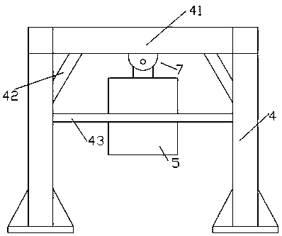
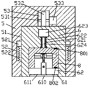
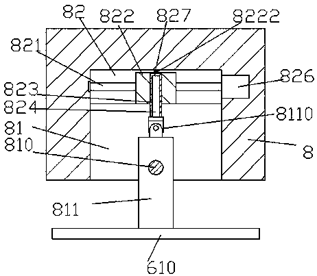
[0018] Such as figure 1 , figure 2 with image 3 As shown, a practical garbage recovery and compression device of the present invention includes an angle adjustment device 7 and a compressor 5 installed at the bottom of the angle adjustment device 7. The bottom surface of the compressor 5 is provided with a first accommodating groove 51, so A sliding compression block 6 is slidably connected to the first accommodation groove 51, and the inner walls on the left and right sides of the first accommodation groove 51 are commensurately provided with guiding devices that are respectively matched and connected to the outer walls on the left and right sides of the sliding compression block 6. The top wall of the first accommodation groove 51 is provided with a compression driving device, the bottom surface of the sliding compression block 6 is provided with a bottom groove 61, and the sliding compression block 6 on the upper side of the bottom groove 61 is provided with a sliding gr...


PUM


Abstract

The invention discloses a practical garbage recovery compression device. The practical garbage recovery compression device comprises an angle adjusting device and a compressor mounted in the bottom ofthe angle adjusting device, wherein a first accommodating groove is formed in the bottom surface of the compressor; a sliding compression block is slidably connected in the first accommodating groovein a matched manner; guiding devices connected to the left and right outer walls of the sliding compression block in a matched manner are symmetrically arranged on the left and right inner walls of the first accommodating groove, separately; a compression driving device is arranged in the top wall of the first accommodating groove; a bottom groove is formed in the bottom surface of the sliding compression block; a sliding groove is formed in the sliding compression block on the upper side of the bottom groove; a passing groove is formed through the sliding compression block between the bottomof the sliding groove and the bottom wall of the bottom groove; a sliding block is slidably connected in the sliding groove in a matched manner; and a driving device slidably connected to the slidingblock in a matched manner is arranged in the top wall of the sliding groove. The practical garbage recovery compression device disclosed by the invention is simple in structure and convenient to operate, and can achieve driving work of automatically operating compressing work, so that the labor amount of workers is reduced and the work efficiency and quality are improved.

Description

technical field [0001] The invention relates to the technical field of garbage compression, in particular to a practical garbage recycling and compression device. Background technique [0002] Properly treated garbage can be turned into resources for secondary use, which neither pollutes the environment, but is also conducive to the recycling and reuse of resources, thereby effectively protecting the environment. General garbage such as waste paper, aluminum cans, and plastic products are processed through compression Manual extrusion is very laborious, difficult to operate and inefficient, and difficult to meet processing needs. The existing garbage compressors can only compress from top to bottom. For some large garbage, it cannot be compressed according to its shape and cannot be adjusted. The angle of compression is not good for practicality. Contents of the invention [0003] The technical problem to be solved by the present invention is to provide a practical garbag...

Claims


Application Information

Patent Timeline
Patent Type & Authority Applications(China)
IPC IPC(8): B30B9/30
CPCB30B9/306B30B9/3032
Inventor 方自根
Owner 方自根
Why Eureka
Try Eureka