Fatigue loading device for in-situ observation of scanning electron microscope

An electron microscope, fatigue loading technology, applied in measurement devices, material analysis using radiation diffraction, material analysis using wave/particle radiation, etc., can solve problems such as failure to achieve fatigue loading, and improve experimental stability and data reliability The effect of stability, small and compact structure design, ensuring stability

Pending Publication Date: 2020-05-12
TIANJIN UNIV
View PDF0 Cites 1 Cited by
  • Summary
  • Abstract
  • Description
  • Claims
  • Application Information

AI Technical Summary

Problems solved by technology

[0004] What the present invention aims to solve is the technical problem that the existing in-situ loading scanning electron microscope technology cannot realize fatigue loading, and provides a fatigue loading device for in-situ observation of scanning electron microscope, which realizes the online in-situ observation of material fatigue test process by SEM The observation of microstructure changes and damage failure behavior breaks the conventional limitations of general in-situ observation of tensile equipment, and can integrate various mechanical test forms such as tension, compression, and fatigue, expanding the application range and scope of in-situ observation of mechanical loading devices. field

Method used


Image

  • Fatigue loading device for in-situ observation of scanning electron microscope
  • Fatigue loading device for in-situ observation of scanning electron microscope
  • Fatigue loading device for in-situ observation of scanning electron microscope

Examples


Embodiment Construction

[0026] In order to further understand the content, characteristics and effects of the present invention, the following examples are given, and detailed descriptions are as follows in conjunction with the accompanying drawings:

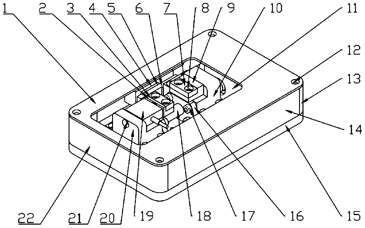
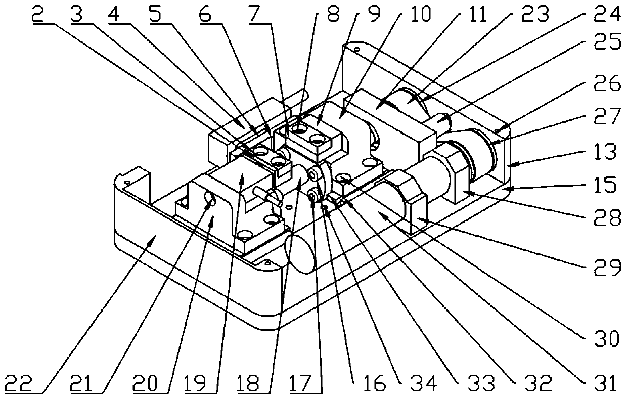
[0027] like figure 1 and figure 2 As shown, this embodiment provides a fatigue loading device for in-situ observation by a scanning electron microscope, which is mainly composed of a structure, a mechanical loading unit, a data acquisition unit, a fixed connection unit and a sealed connection unit.

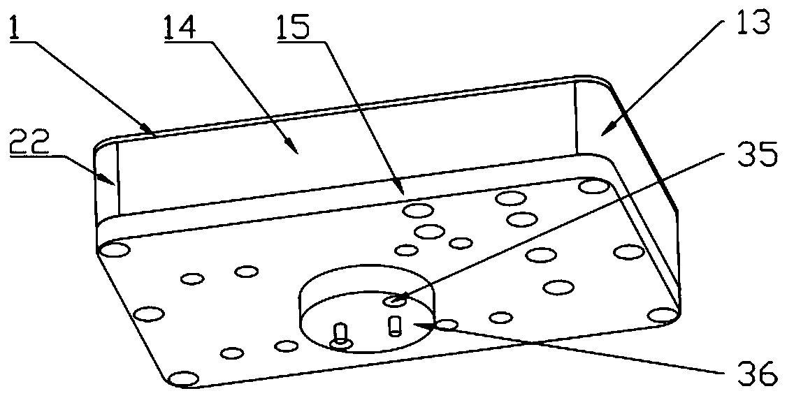
[0028] The structural body includes an outer cover plate, a middle support plate 11 , a pulley fixing block 28 and a motor fixing block 29 . The mechanical loading unit and the data acquisition unit are arranged inside the outer cover plate, and the outer cover plate mainly plays a shielding role. The outer cover consists of an upper cover plate 1 at the top, a base plate 15 at the bottom, side cover plates 14 at both sides, first support plates 13 and ...


PUM


Abstract

The invention belongs to the field of mechanical property testing of materials, and discloses a fatigue loading device for in-situ observation of a scanning electron microscope, which mainly comprisesa structural body, a mechanical loading unit, a data acquisition unit, a fixed connection unit and a sealed connection unit, wherein the mechanical loading unit and the data acquisition unit are arranged in the structural body; the mechanical loading unit comprises a motor, a first belt wheel, a conveying belt, a second belt wheel, a belt pressing wheel, a lead screw, a nut ejector block and a clamp set; the data acquisition unit comprises a grating ruler, a reading head and a load sensor; the fixed connection unit is arranged at the bottom of the structural body; and the sealed connection unit is arranged at a wire outlet of an SEM sample chamber. Thus, the observation of microstructure change and damage failure behaviors in the SEM online in-situ observation material fatigue test process is realized, the conventional limitation of general in-situ observation stretching equipment is broken through, and various mechanical test forms such as stretching, compression and fatigue can be integrated.

Description

technical field [0001] The invention belongs to the field of material mechanical performance testing, and in particular relates to a fatigue loading device for material dynamic mechanical microstructure characterization and performance testing. Background technique [0002] The mechanical properties of materials are one of the key issues in many of their properties, which is of great significance for the wide application of materials. Therefore, the study of the mechanical properties of materials has become an important work in material science research. In recent years, the micromechanics research method of analyzing and studying the factors affecting the mechanical properties of materials from the microscopic scale has become a hot field in the research of mechanical properties of materials. After assembling an additional loading device with functions such as tension, compression, bending, and shearing in the scanning electron microscope, the loading effect can be combine...

Claims


Application Information

Patent Timeline
Patent Type & Authority Applications(China)
IPC IPC(8): G01N23/04G01N23/20G01N23/20008G01N3/32G01N3/02
CPCG01N3/02G01N3/32G01N23/04G01N23/20G01N23/20008
Inventor 陈刚冯少武林强
Owner TIANJIN UNIV
Why Eureka
Try Eureka