Circularl polarization-type polarization diversity element, scanning element using same, and lidar

A technology of polarization diversity and laser radar, which is applied in polarizing elements, optical elements, optics, etc., can solve problems such as inability to scan at high speeds, and achieve excellent mass production and reduce the effect of temperature

Active Publication Date: 2020-05-12
NAT INST OF ADVANCED IND SCI & TECH
View PDF17 Cites 3 Cited by
  • Summary
  • Abstract
  • Description
  • Claims
  • Application Information

AI Technical Summary

Problems solved by technology

However, in the above-mentioned conventional scanning device, the same scanning is performed, and high-speed scanning of any point cannot be programmed with any frequency and any pattern.

Method used


Image

  • Circularl polarization-type polarization diversity element, scanning element using same, and lidar
  • Circularl polarization-type polarization diversity element, scanning element using same, and lidar
  • Circularl polarization-type polarization diversity element, scanning element using same, and lidar

Examples


Embodiment 1

[0072] Figure 7 An example of the circular polarization type polarization diversity element 71 of the present invention is shown. The light beam 32 emitted from the single-mode fiber 31 is collimated using the lens 2. The polarization state can be decomposed into right-handed circularly polarized light (corresponding to m=+1: solid line) and left-handed circularly polarized light (corresponding to m=-1: dashed line). If the light beam 32 then enters the polarization grating 92, the right-handed circularly polarized light becomes upward (deflection), and the left-handed circularly polarized light becomes downward (deflection), which are respectively converted into reversely rotated circularly polarized light.

[0073] Figure 8 The structure and function of the polarization grating 92 are shown. The polarization grating 92 is made of, for example, a liquid crystal polymer or the like, and its guide rotates along the rotation axis A at a specific period Λ. The thickness is set s...

Embodiment 2

[0086] Figure 9A~Figure 9C An example of a beam digital scanning element using the circular polarization type polarization diversity element 71 is shown. Figure 9A Represents the beam digital scanning element, Figure 9B Represents the basic unit. In addition, Figure 9C This is an enlarged view showing the structure of the part surrounded by the one-point chain line A of the polarization turning element 91. Figure 9A The beam digital scanning element 90 shown is Figure 9B The illustrated basic unit 94 is formed by connecting a plurality of stages with a required number of groups, and a circular polarization type polarization diversity element 71 and a lens 2 are arranged.

[0087] As for Figure 9B and Figure 9C As explained, the basic unit 94 is formed by sandwiching the polarization turning element 91 in a point symmetrical manner by a wedge 93 composed of two high refractive index materials. The polarization turning element 91 is formed by forming a transparent glass subst...

Embodiment 3

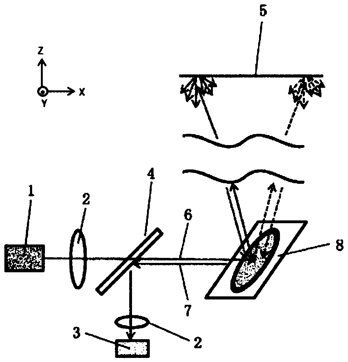
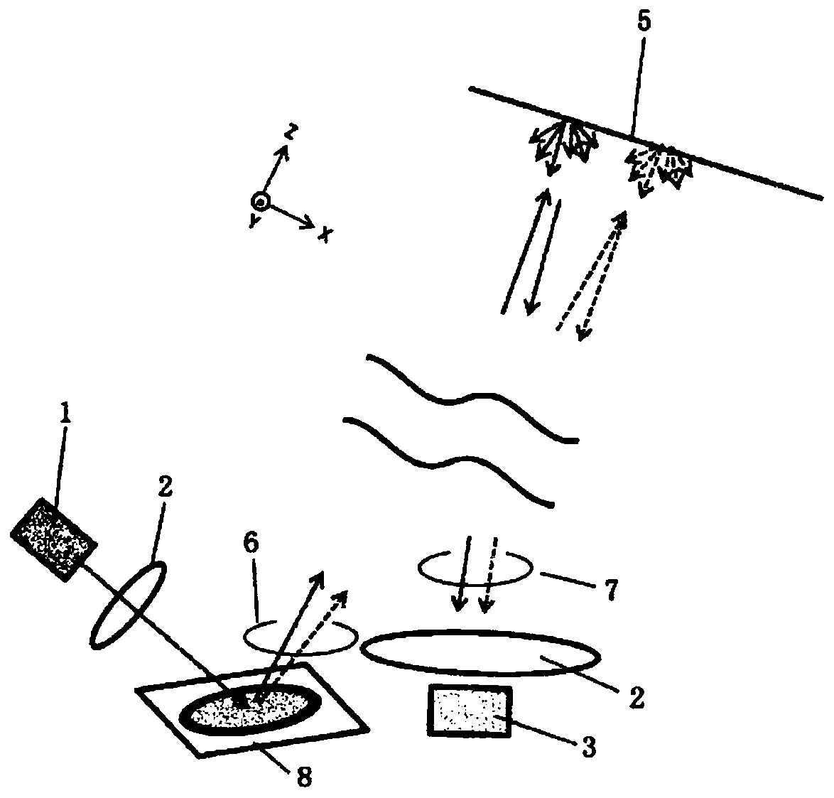
[0101] Picture 11 To show an example of a lidar capable of performing the above-mentioned scanning. The composition of this lidar is similar to the above figure 2 The same coaxial system uses a transmissive beam digital scanning element 90 in the steering element instead of the reflective microelectromechanical mirror 8.

[0102] On the other hand, as a modulation method of lidar, there are various reports. In this embodiment, the Time of Flight (ToF) method is used as the modulation method. This method measures the time difference T from the transmission of the light pulse 9 (reception of the transmitted light pulse 9 by the light receiving element 3) to the reception of the light pulse 10 (reception by the light receiving element 3), according to d=cT / 2 (here , C is the speed of light) to measure the distance d to the object 5. Among them, T is appropriately corrected by the optical path length formed by the lidar.

[0103] In order to improve the distance accuracy, electron...


PUM


Abstract

In the prior art, a scanning element used in the autonomous driving car technology of Lidar has inertia due to continuously rotating a mirror or the like by MEMS, and thus is for a raster scan that scans a scene all at once. Such a scanning element was not capable of moving discontinuously from an arbitrary point to another arbitrary point, and performing a high-speed scan that is programmable toan arbitrary frequency and an arbitrary pattern and equivalent to the raster scan. According to the present invention, a Lidar is manufactured comprising a scanning element in which: two polarizationgratings, which have a double refraction director with a thickness corresponding to a half-wavelength plate and rotate with a period ^, are used spaced apart at a desired interval; and a polarizationdiversity method, in which the half-wavelength plate is inserted in the path of one among two light beams, that is, a clockwise-circularly polarized light beam and a counterclockwise-circularly polarized light beam, separately emitted according to the rotation direction of the circularly polarized light, is adopted to achieve a conversion into parallel and proximate circularly polarized light beams having the same rotation direction, wherein the scanning element combines structures in which pairs of a polarization switch and the polarization grating are connected in multiple stages.

Description

Technical field [0001] The invention relates to a circularly polarized light element and a beam digital scanning element, as well as a laser radar and scanning method using the same. Background technique [0002] figure 1 This is an example of polarization diversity as a conventional polarization control technology (Patent Document 1). After being split into two orthogonal linear polarized lights by the polarization beam splitter 102, they are rotated by the polarization rotating element 107 in one optical path, so that the polarization of the light transmitted in the two optical paths is the same (here, the linear vibrating in the vertical direction). Polarized light). However, this polarization diversity method is effective for devices that operate by linear polarization, and devices that operate by circular polarization cannot be used. [0003] on the other hand, figure 2 The configuration of a laser radar using a microelectromechanical mirror 8 as a conventional scanning ele...

Claims


Application Information

Patent Timeline
Patent Type & Authority Applications(China)
IPC IPC(8): G02B5/30G01S7/481G02F1/29
CPCG01S7/4817G01S7/499G01S17/931G01S7/4812G01S7/4917G01S17/10G01S17/34G01S7/4814G02B27/283G02B27/4261G02B26/101G02F1/29G02B27/286G01S17/89G02B5/3025
Inventor 上塚尚登
Owner NAT INST OF ADVANCED IND SCI & TECH
Why Eureka
Try Eureka