Supercharge Your Innovation With Domain-Expert AI Agents!

Integral inclined block mechanical compensation workbench

A workbench and integral technology, applied in the field of integral inclined block mechanical compensation workbench, can solve the problems of insufficient machining accuracy, the influence of installation holes and inclined block compensation accuracy, etc., to achieve convenient operation, avoid displacement errors, and improve compensation accuracy. Effect

Inactive Publication Date: 2020-05-15
黄石三锐精密制造有限公司
View PDF0 Cites 0 Cited by
  • Summary
  • Abstract
  • Description
  • Claims
  • Application Information

AI Technical Summary

Problems solved by technology

[0003] The purpose of the present invention is to solve the problem that the gap between the installation hole and the inclined block has a great influence on the compensation accuracy due to the insufficient machining accuracy of the existing split inclined block mechanical compensation structure, and to provide an integral inclined block mechanical compensation workbench

Method used


Image

  • Integral inclined block mechanical compensation workbench
  • Integral inclined block mechanical compensation workbench
  • Integral inclined block mechanical compensation workbench

Examples


Embodiment 1

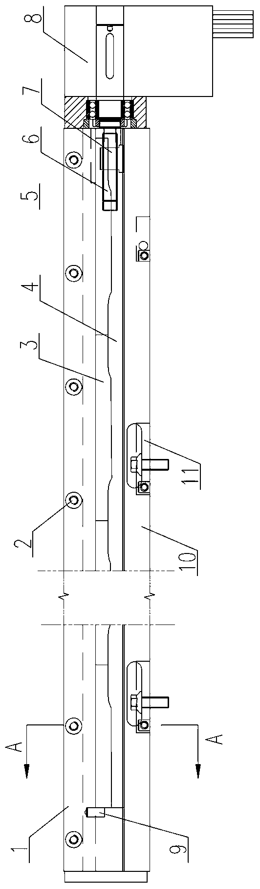
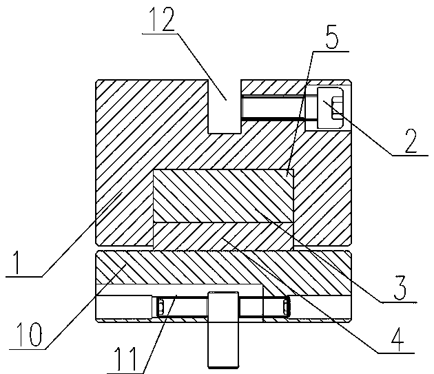
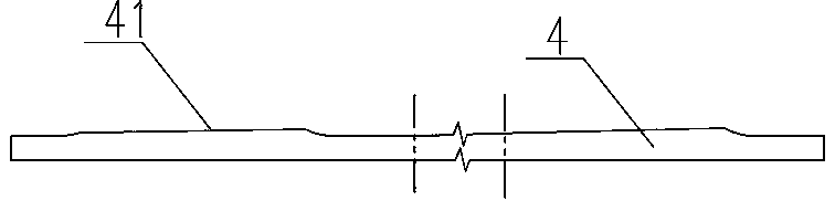
[0016] See Figure 1-4 This embodiment includes a long base 10, the bottom of the base 10 is provided with a mounting hole 11 for fixing with the frame of the bending machine, the top of the base 10 is equipped with a mold mounting seat 1, and the bottom of the mold mounting seat 1 is provided with a recess along the full length Slot 5, a drive plate 4 is installed in the groove 5 on the top surface of the base. One end of the drive plate 4 is fixed with a nut 7, and the outer end of the base 10 is equipped with a motor 8, and the output shaft of the motor 8 is equipped with a nut 7 7 Threaded screw 6, the drive plate 4 is provided with a number of inclined surfaces 41 along the length direction. Among them, the inclined surface 41 in the middle has the largest inclination angle, and the inclined surface 41 at both ends gradually decreases. The top of each inclined surface 41 is matched An upper inclined block 3, the bottom of the upper inclined block 3 is provided with an incl...

Embodiment 2

[0019] See Figure 5 The mechanism of this embodiment is basically the same as that of the first embodiment. The difference is that the mold mounting seat 1 is located on the side of the mold mounting groove 12 and is equipped with a hydraulic clamping mechanism for clamping the mold. The hydraulic clamping mechanism includes a mold mounting seat 1 A row of several piston holes 13 arranged in the longitudinal direction, one end of the piston hole 13 faces the mold mounting groove 12, each piston hole 13 is equipped with a piston rod 15 matching the piston hole 13, and the mold mounting seat 1 is provided with a line along the length The hydraulic oil hole 14 is arranged, the hydraulic oil hole 14 is communicated with all the piston holes 13, and one end of the hydraulic oil hole 14 is communicated with the outside for installing the hydraulic oil pipe connected with the oil pump.

[0020] The piston hole 13 in this embodiment has an inward step, and a spring 16 for resetting the p...


PUM


Abstract

The invention relates to the technical field of bending machine turbulence mechanical compensation, in particular to an integral inclined block mechanical compensation workbench. The integral inclinedblock mechanical compensation workbench comprises a long base, wherein the bottom surface of the base is provided with a mounting hole for fixing to a bending machine frame, the top of the base is provided with a die mounting seat, and the bottom surface of the die mounting seat is provided with a groove along the whole length. The integral inclined block mechanical compensation workbench is characterized in that a transmission plate is arranged at the position, located on the top surface of the base, of the interior of the groove, a nut is fixedly arranged at one end of the transmission plate, a motor is arranged at the outer end of the base, a screw rod in threaded connection with the nut is arranged on an output shaft of the motor, a plurality of inclined planes are arranged on the transmission plate in the length direction, the inclined angle of the inclined plane in the middle is the largest, the inclined angles of the inclined planes at the two ends are gradually reduced, an upper inclined block is arranged at the top of each inclined plane in a matched mode. an inclined plane matched with the transmission plate is arranged at the bottom of each upper inclined block, and thetop surface of each upper inclined block is attached to the top surface of the groove. The integral inclined block mechanical compensation workbench improves the compensation precision.

Description

Technical field [0001] The invention relates to the technical field of disturbance mechanical compensation for bending machines, in particular to an integral inclined block mechanical compensation workbench. Background technique [0002] During the bending process of the bending machine, the bottom of the slider will produce upward disturbance deformation. In order to improve the bending accuracy, the worktable under the slider is designed as a compensation mechanism that can compensate for this deformation. Most of the existing compensation mechanisms use split The oblique block type mechanical compensation structure is driven by the motor to drive the lower oblique block to slide horizontally to drive the upper oblique block to go up and down. The different groups of oblique blocks have different lifting heights to form a curve complementary to the disturbance and deformation of the slider, thereby realizing mechanical compensation. Type mechanical compensation structure has th...

Claims


Application Information

Patent Timeline
Patent Type & Authority Applications(China)
IPC IPC(8): B21D11/22
CPCB21D11/22
Inventor 郑正军徐林
Owner 黄石三锐精密制造有限公司
Features
  • R&D
  • Intellectual Property
  • Life Sciences
  • Materials
  • Tech Scout
  • Unparalleled Data Quality
  • Higher Quality Content
  • 60% Fewer Hallucinations
Learn More