Self-balancing foundation load test device
A load test and self-balancing technology, which is applied in basic structure engineering, on-site foundation soil survey, construction, etc., can solve the problems of inaccurate test data, complicated device structure, complicated operation, etc., and achieve high test efficiency and equipment design. The effect of compactness and accurate test data
- Summary
- Abstract
- Description
- Claims
- Application Information
AI Technical Summary
Problems solved by technology
Method used
Image
Examples
Embodiment 1
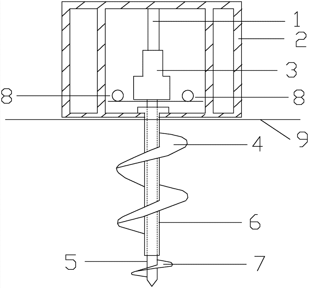
[0033] Such as figure 1 As shown, a self-balancing foundation load test device includes a reaction force system, a force transmission system and a test system. The reaction force system includes a reaction force frame 2 of a square cage structure, a reaction force anchor rod 6 and a reaction force anchor blade 4 The force transmission system includes a jack 3 and a dowel bar 5; the test system includes a stress gauge 1, a dial indicator 8 and a spiral test plate 7; A counterforce anchor blade 4 is provided, and a dowel bar 5 whose length exceeds the counterforce anchor bar 6 at both ends is pierced in the counterforce anchor bar 6, and a spiral test plate 7 is provided outside the lower end of the dowel bar 5, and the upper end of the dowel bar 5 The end face is connected to the jack 3, and the upper part of the jack 3 is provided with a stress gauge 1, and the upper end of the stress gauge 1 is placed on the inner top plate of the reaction frame 2; the dial indicator 8 is pla...
Embodiment 2
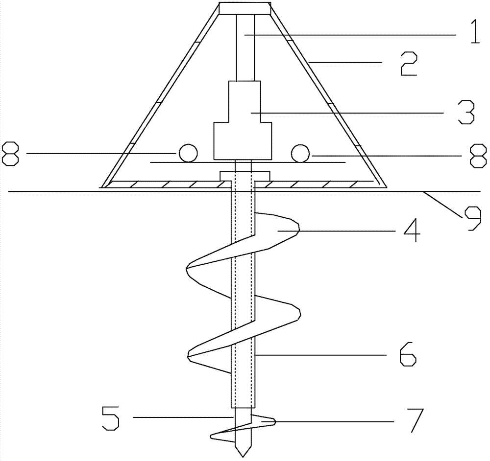
[0047] Such as figure 2As shown, a self-balancing foundation load test device includes a reaction force system, a force transmission system and a test system. The reaction force system includes a reaction force frame 2 with a triangular umbrella structure, a reaction force anchor rod 6 and a reaction force anchor blade 4 The force transmission system includes a jack 3 and a dowel bar 5; the test system includes a stress gauge 1, a dial indicator 8 and a spiral test plate 7; A counterforce anchor blade 4 is provided, and a dowel bar 5 whose length exceeds the counterforce anchor bar 6 at both ends is pierced in the counterforce anchor bar 6, and a spiral test plate 7 is provided outside the lower end of the dowel bar 5, and the upper end of the dowel bar 5 The end face is connected to the jack 3, and the upper part of the jack 3 is provided with a stress gauge 1, and the upper end of the stress gauge 1 is placed on the inner top plate of the reaction frame 2; the dial indicato...
PUM
 Abstract
Description
Claims
Application Information
 - R&D
- Intellectual Property
- Life Sciences
- Materials
- Tech Scout
- Unparalleled Data Quality
- Higher Quality Content
- 60% Fewer Hallucinations
Browse by: Latest US Patents, China's latest patents, Technical Efficacy Thesaurus, Application Domain, Technology Topic, Popular Technical Reports.
© 2025 PatSnap. All rights reserved.Legal|Privacy policy|Modern Slavery Act Transparency Statement|Sitemap|About US| Contact US: help@patsnap.com


