Bionic feet of quadruped robot

A quadruped robot and forefoot technology, applied in motor vehicles, transportation and packaging, etc., can solve the problems of restricting the development of quadruped robots and single functions, and achieve the effect of improving stability and expanding the scope of application

Inactive Publication Date: 2020-05-15
NANJING HANXIYUE AUTOMATION TECH CO LTD
View PDF5 Cites 3 Cited by
  • Summary
  • Abstract
  • Description
  • Claims
  • Application Information

AI Technical Summary

Problems solved by technology

[0003] Most of the existing quadruped robots adopt the single-function manufacturing concept, and the bionic feet of quadruped robots cannot be made to realize both walking and running of the robot, which limits the development of quadruped robots, so we propose a A quadruped robot bionic foot, in order to solve the problems raised above

Method used


Image

  • Bionic feet of quadruped robot
  • Bionic feet of quadruped robot
  • Bionic feet of quadruped robot

Examples


Embodiment 1

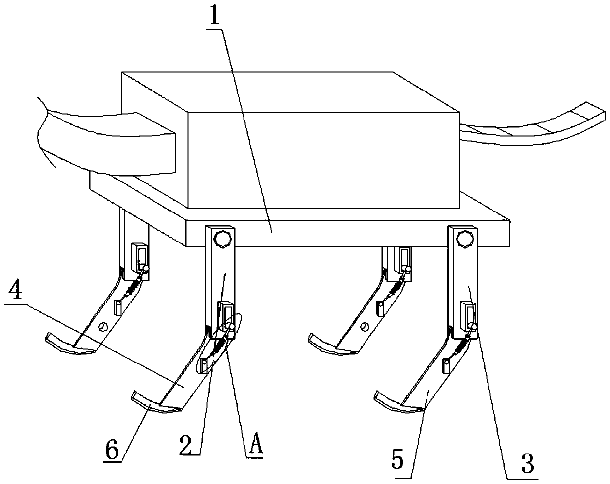
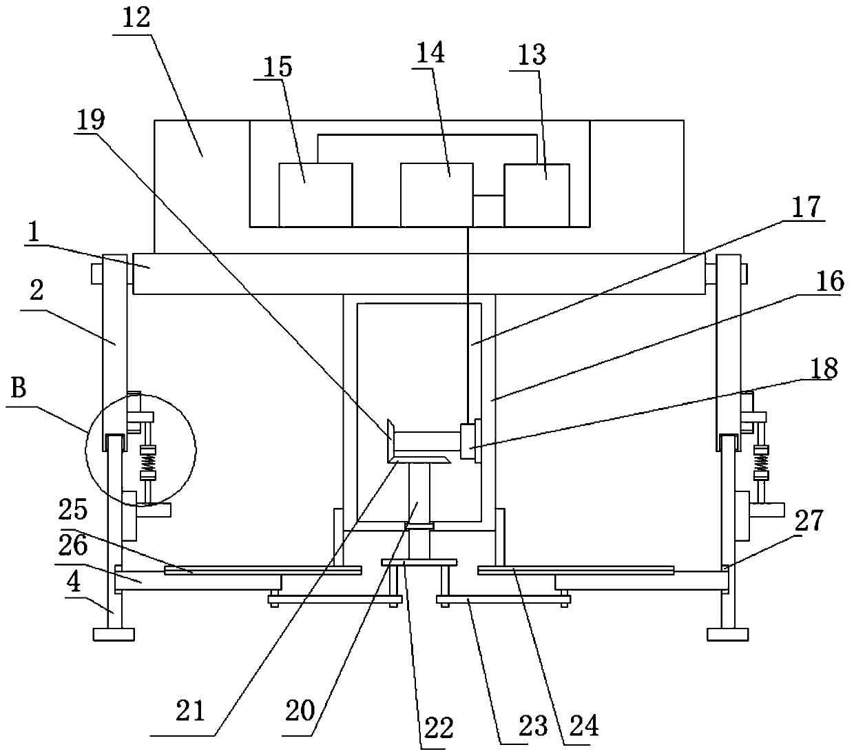
[0030] see Figure 1-3 , the present embodiment provides a bionic foot for a quadruped robot, including a mounting plate 1, symmetrical front feet 2 and rear feet 3 are fixedly installed on both sides of the mounting plate 1, and the bottoms of the front foot 2 and rear foot 3 are interactively installed respectively There is a first movable arm 4 and a second movable arm 5, and a buffer mechanism is arranged between the first movable arm 4 and the second movable arm 5 and their movably installed forefoot 2 or rear foot 3 respectively, and the top of the mounting plate 1 is fixedly installed There is a top block 12, the bottom of the mounting plate 1 is fixedly equipped with a vertical block 16, the vertical block 16 is provided with a chamber 17, the bottom of the vertical block 16 is rotatably equipped with a vertical shaft 20, and the bottom of the vertical shaft 20 is fixedly equipped with a turntable 22, The bottom of the turntable 22 is movably installed with two connect...

Embodiment 2

[0034] see Figure 1-3 , further improvements have been made on the basis of Example 1:

[0035] The top of the top block 12 is provided with a placement groove, and the bottom inner wall of the placement groove is fixedly installed with a walking driving mechanism 15, a running driving mechanism 14 and a controller 13 successively, and the walking driving mechanism 15 and the running driving mechanism 14 are electrically connected to the controller 13. connected, the two functions of walking and running are individually controlled through the set controller 13;

[0036] The drive mechanism includes a drive motor 18 fixed on the inner wall of one side of the chamber 17. The drive motor 18 is electrically connected to the controller 13. One end of the output shaft of the drive motor 18 is fixedly sleeved with a first bevel gear 19. The top of the vertical shaft 20 is Through the top of the vertical block 16 and extending into the chamber 17, the outer side of the vertical shaft ...


PUM


Abstract

The invention discloses bionic feet of a quadruped robot. The bionic feet comprise a mounting plate, wherein front feet and rear feet which are symmetrically arranged are fixedly mounted on the two sides of the mounting plate; first movable arms and second movable arms are respectively and interactively mounted at the bottoms of the front feet and the rear feet; buffering mechanisms are arranged between the first movable arms and the front feet or between the second movable arms and the rear feet movably installed on the first movable arms and the second movable arms; a top block is fixedly installed at the top of the mounting plate; a vertical block is fixedly installed at the bottom of the mounting plate; a cavity is formed in the vertical block; a vertical shaft is rotationally installed at the bottom of the vertical block; and a rotary disc is fixedly installed at the bottom of the vertical shaft. According to the bionic feet of the quadruped robot, the walking function and the running function of the bionic feet are combined into a whole; the bionic feet are capable of walking and running, the application range of the bionic feet is expanded, a great progress is achieved in the bionic aspect of the quadruped robot, and a precious practice foundation is provided for development of the quadruped robot in the future.

Description

technical field [0001] The invention relates to the technical field of quadruped robots, in particular to a bionic foot of a quadruped robot. Background technique [0002] From the "Wooden Cow and Flowing Horse" invented by Zhuge Liang during the Three Kingdoms period of China to the LS3 nicknamed "Alpha Dog" robot developed by Boston Dynamics, robots have always demonstrated their ability to adapt to harsh environments. Industry, search and rescue detection and other fields play a huge role. [0003] Most of the existing quadruped robots adopt the single-function manufacturing concept, and the bionic feet of quadruped robots cannot be made to realize both walking and running of the robot, which limits the development of quadruped robots, so we propose a A quadruped robot bionic foot is provided to solve the above-mentioned problems. Contents of the invention [0004] The purpose of the present invention is to provide a quadruped robot bionic foot to solve the problems r...

Claims


Application Information

Patent Timeline
Patent Type & Authority Applications(China)
IPC IPC(8): B62D57/032
CPCB62D57/032
Inventor 李勇许杰兴王太裕
Owner NANJING HANXIYUE AUTOMATION TECH CO LTD
Why Eureka
Try Eureka