Auxiliary turning device for bed-ridden examination of people

A technology of personnel and auxiliary side, applied in the field of auxiliary turning devices, can solve the problems of complicated operation, unreliable fixation, inability to lock and fix, etc., and achieve the effects of avoiding bump injury, convenient standing up inspection, and reasonable structure design.

Inactive Publication Date: 2020-05-19
肖梅
View PDF8 Cites 10 Cited by
  • Summary
  • Abstract
  • Description
  • Claims
  • Application Information

AI Technical Summary

Problems solved by technology

[0002] During the care and treatment of patients in the hospital bed, doctors need to check the diseased parts in time to better understand the condition and ensure the treatment effect. For doctors who need to use special auxiliary turning devices to support people when they are bedridden, but the traditional There are many deficiencies in the auxiliary turning device used for bedridden inspection. The bed body is inconvenient to move, cannot be locked or fixed enough, and the operation is cumbersome. For patients who are not allowed to move and adjust, they cannot provide supine and side turning during inspection. For patients who can move by themselves, they cannot get up with the best strength according to the length of their hands, and cannot meet the needs of use, which makes it inconvenient for doctors to examine bedridden patients, resulting in difficulty in examination, limited examination surface, and poor structure. The design is not reasonable enough, and it cannot effectively avoid collision damage caused by excessive movement range. When the structure is reset, it cannot achieve good shock absorption, buffering and limit support, so that it cannot give patients sufficient comfort considerations, so it can solve such problems. It is imperative to realize an auxiliary turning device for bedridden examination of the problem

Method used


Image

  • Auxiliary turning device for bed-ridden examination of people
  • Auxiliary turning device for bed-ridden examination of people
  • Auxiliary turning device for bed-ridden examination of people

Examples


Embodiment Construction

[0030] The following will clearly and completely describe the technical solutions in the embodiments of the present invention with reference to the accompanying drawings in the embodiments of the present invention. Obviously, the described embodiments are only some, not all, embodiments of the present invention. Based on the embodiments of the present invention, all other embodiments obtained by persons of ordinary skill in the art without making creative efforts belong to the protection scope of the present invention.

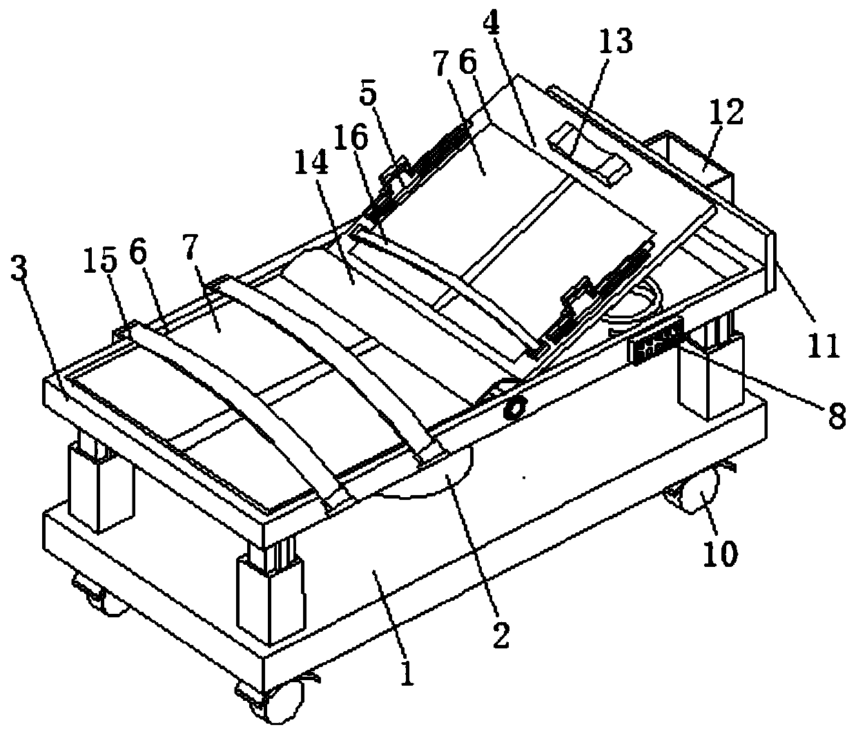
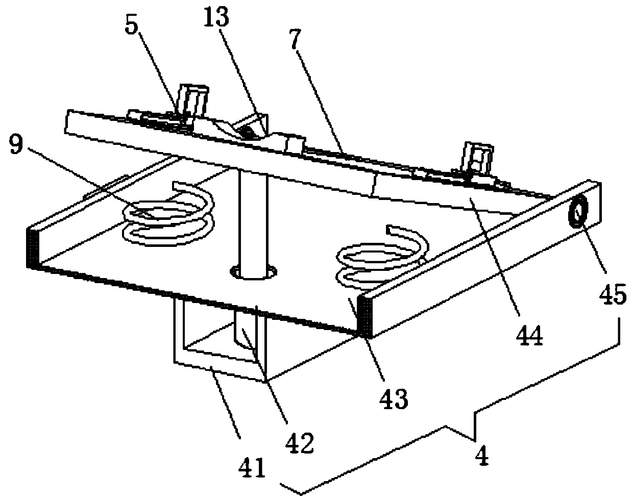
[0031] see Figure 1-6 , the present invention provides a technical solution: an auxiliary turning device for bedridden inspection, comprising a base plate 1, an auxiliary lifting structure 2, a supine turning structure 4, an auxiliary turning structure 5 and an auxiliary rolling structure 7;

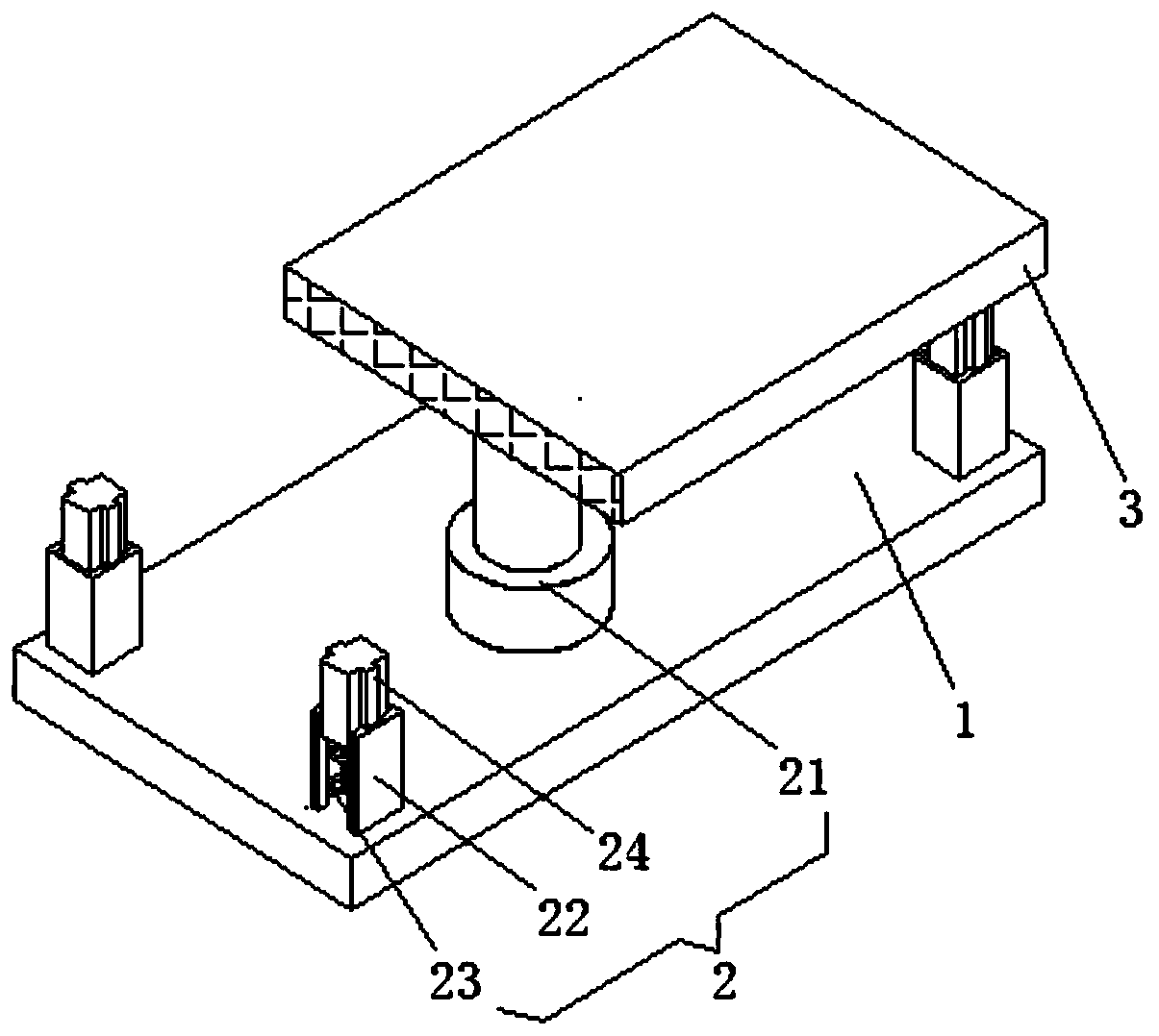
[0032] Bottom plate 1: Bottom plate 1 is a stainless steel bottom plate, and bottom plate 1 provides bottom support and placement;

[0033] Auxiliary lifting structure 2...


PUM


Abstract

The invention discloses an auxiliary turning device for bed-ridden examination of people. The device comprises a bottom plate, an auxiliary lifting structure, a supine turning structure, auxiliary turning structures and an auxiliary side turning structure, the bottom plate is a stainless steel bottom plate, the auxiliary lifting structure is arranged at the upper end of the bottom plate, a bed plate is arranged at the upper end of the auxiliary lifting structure, the supine turning structure is arranged on the right side of the upper end of the bed plate, grooves are formed in the middle of the upper end of the supine turning structure and the left side of the upper end of the bed plate, and the auxiliary turning structures are symmetrically arranged on the left and right sides of the upper end of the supine turning structure. The auxiliary turning device for bed-ridden examination of people is simple in structure, convenient to move, firm in fixation and easy to operate, can provide assistance for supine turning over and side turning over in the examination process and optimally exert force to get up according to the hand length condition, meets the use requirements, can help doctors to more comprehensively examine bedridden patients, is reasonable in structural design, and gives full comfort consideration to the patients.

Description

technical field [0001] The invention relates to the technical field of medical auxiliary equipment, in particular to an auxiliary turning device for bedridden examination of personnel. Background technique [0002] During the care and treatment of patients in the hospital bed, doctors need to check the diseased parts in time to better understand the condition and ensure the treatment effect. For doctors who need to use special auxiliary turning devices to support people when they are bedridden, but the traditional There are many deficiencies in the auxiliary turning device used for bedridden inspection. The bed body is inconvenient to move, cannot be locked or fixed enough, and the operation is cumbersome. For patients who are not allowed to move and adjust, they cannot provide supine and side turning during inspection. For patients who can move by themselves, they cannot get up with the best strength according to the length of their hands, and cannot meet the needs of use, ...

Claims


Application Information

Patent Timeline
Patent Type & Authority Applications(China)
IPC IPC(8): A61G7/05
CPCA61G7/001A61G7/05
Inventor 肖梅
Owner 肖梅
Why Eureka
Try Eureka