Check valve

A technology for check valves and valve chambers, applied in sliding valves, valve details, control valves, etc., can solve problems such as valve damage, high impact force on the sealing surface of the valve seat, and easy water hammer, etc., so as to prolong the service life and avoid The effect of water hammer

Active Publication Date: 2020-05-19
ZHEJIANG OFILM PETROLEUM EQUIP CO LTD
View PDF7 Cites 3 Cited by
  • Summary
  • Abstract
  • Description
  • Claims
  • Application Information

AI Technical Summary

Problems solved by technology

It is used to connect and check the fluid medium in the pipeline system, and is widely used in industrial equipment. The existing traditional check valve disc is prone to excessive closing speed during the process of rotating and closing around the pin shaft, resulting in The impact force of the disc sealing surface on the sealing surface of the valve seat is too large, which is easy to be damaged; at the same time, when the check valve disc is closed quickly, it is easy to generate water hammer, resulting in damage to the valve and other harmful situations; Used together with the flow valve, due to the wide variety of valves, a large installation space is required, the traditional check valve can no longer meet the needs of the actual working conditions

Method used


Image

  • Check valve
  • Check valve
  • Check valve

Examples


Embodiment Construction

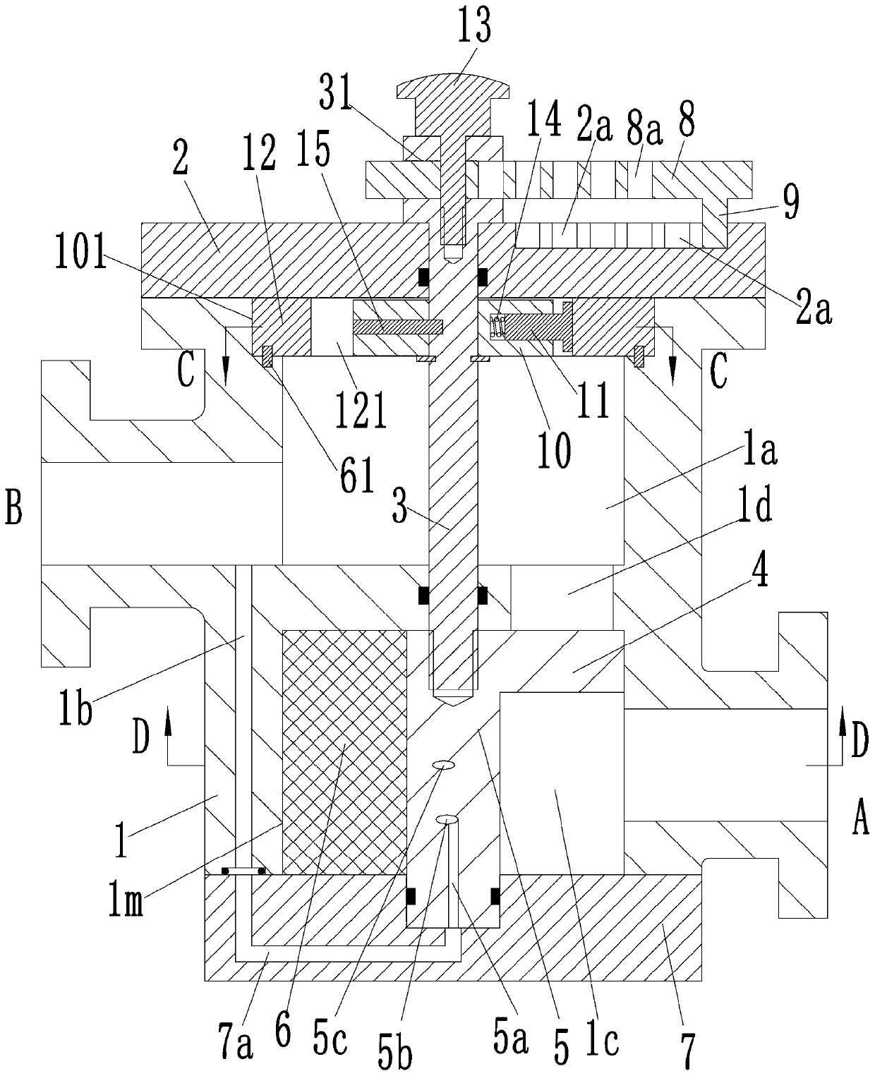
[0024] see Figure 1-6 As shown, a check valve includes a valve body 1, the valve body 1 is provided with an upper valve chamber 1a and a lower valve chamber 1m, and the valve body 1 is provided with a valve for communicating with the upper valve chamber 1a and the lower valve chamber. 1m valve port 1d; the side of the valve body 1 is provided with a B port communicating with the upper valve chamber 1a, and a port A communicating with the lower valve chamber 1m; the valve body 1 is at the upper opening of the upper valve chamber 1a The upper end cover 2 is fixedly installed, and the lower end cover 7 is fixedly installed at the lower end opening of the lower valve chamber 1m.

[0025] In the lower valve chamber 1m, a rotating shaft 5 is rotatably connected between the top of the lower end cover 7 and the lower valve chamber 1m, and the rotating shaft 5 is coaxially arranged with the lower valve chamber 1m; On the surface, a first baffle plate 7c and a second baffle plate 7b a...


PUM


Abstract

The invention discloses a check valve comprising a valve body. An upper valve cavity and a lower valve cavity are formed in the valve body. A valve opening used for making the upper valve cavity and the lower valve cavity communicate is formed in the valve body. A port B communicating with the upper valve cavity and a port A communicating with the lower valve cavity are formed in the side face ofthe valve body. An upper end cover is fixedly installed on the portion, at the position of an upper end opening of the upper valve cavity, of the valve body. A lower end cover is fixedly installed onthe portion, at the position of a lower end opening of the lower valve cavity, of the valve body. A rotating shaft is connected in the lower valve cavity in a rotating manner. The lower end cover is provided with a first baffle and a second baffle. The lower valve cavity is divided into a first sealed cavity and a second cavity, communicating with the port A, through the first baffle and the second baffle. A power plate extending into the first sealed cavity is arranged on the circumferential side face of the rotating shaft. A flow regulation assembly is arranged on the upper end cover. A buffer assembly is arranged in the upper valve cavity. The check valve is simple in structure, flow control can be conducted, and furthermore the valve opening can also be slowly closed.

Description

technical field [0001] The invention belongs to the technical field of pipeline valves, and in particular relates to a check valve. Background technique [0002] Check valve is a kind of valve commonly used in pipeline system. It is used to connect and check the fluid medium in the pipeline system, and is widely used in industrial equipment. The existing traditional check valve disc is prone to excessive closing speed during the process of rotating and closing around the pin shaft, resulting in The impact force of the disc sealing surface on the sealing surface of the valve seat is too large, which is easy to be damaged; at the same time, when the check valve disc is closed quickly, it is easy to generate water hammer, resulting in damage to the valve and other harmful situations; Used together with the flow valve, due to the wide variety of valves, a large installation space is required, and the traditional check valve can no longer meet the needs of the actual working con...

Claims


Application Information

Patent Timeline
Patent Type & Authority Applications(China)
IPC IPC(8): F16K15/03F16K3/06F16K3/32F16K47/02
CPCF16K15/03F16K3/0218F16K3/06F16K3/32F16K47/023
Inventor 邵立坤
Owner ZHEJIANG OFILM PETROLEUM EQUIP CO LTD
Why Eureka
Try Eureka