
Gas stove with automatic cooling igniter and control method thereof

A technology of automatic cooling and control method, applied in the field of gas stoves, can solve the problems of reducing the service life of components, damage, temperature rise, etc., and achieve the effect of prolonging the service life and ensuring stable performance

Pending Publication Date: 2020-05-19
VATTI CORP LTD
View PDF12 Cites 0 Cited by
  • Summary
  • Abstract
  • Description
  • Claims
  • Application Information

AI Technical Summary

Problems solved by technology

When the internal temperature rise of the cooker is high, the temperature of the igniter shell inside the cooker and the internal components will also rise accordingly. When the temperature exceeds the operating temperature limit of the components, it will cause damage to the components and reduce the temperature of the components. service life, reducing the reliability of the igniter, or even direct damage can not be used
Therefore, if the internal temperature of the cooker is too high during use, the igniter may fail or even be damaged due to excessive temperature rise.

Method used


Image

  • Gas stove with automatic cooling igniter and control method thereof
  • Gas stove with automatic cooling igniter and control method thereof
  • Gas stove with automatic cooling igniter and control method thereof

Examples


Embodiment 1

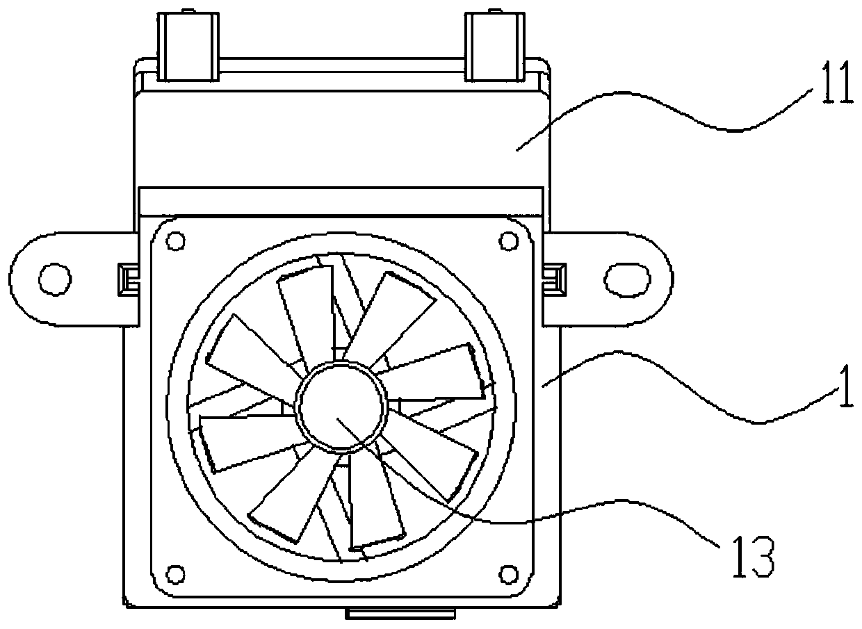
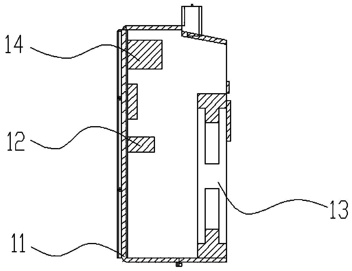
[0023] Participate in the attached Figure 1-3 A gas stove with an igniter capable of automatically cooling down according to the present invention includes a gas stove body, and an igniter 1 is provided in the gas stove body. The igniter 1 includes a housing 11, a controller 12, and a heat sink 13 and a temperature measuring component, the controller 12 is arranged in the housing 11, the heat sink 13 and the temperature measuring component are both arranged on the housing 11, and the controller 12 is respectively connected to the The heat sink 13 and the temperature measuring component are electrically connected. Preferably, a ventilation hole 15 is provided on the housing 11, so that the heat dissipation effect is better. Preferably, the heat dissipation device 13 is a heat dissipation fan, and an opening is provided on the housing 11, and the heat dissipation fan is installed in the opening. A heat dissipating device 13 is provided on the housing 11 of the igniter 1 to act...

Embodiment 2

[0027] Participate in the attached Figure 4 Shows a control method of a gas stove with an automatic cooling igniter of the present invention, which is applied to the gas stove in Embodiment 1. The control method includes the following steps: detecting whether there is an ignition signal S1; if there is an ignition signal , Then detect whether the ignition is successful S2; if the ignition is successful, detect the real-time temperature S3 in the igniter; determine whether the real-time temperature is higher than the preset maximum temperature S4; if the real-time temperature is higher than the preset maximum temperature, start the heat sink S5. In this embodiment, the preset maximum temperature is 85°C.

[0028] After starting the heat dissipation device, it also includes the following steps: detecting whether the real-time temperature in the igniter is lower than the preset minimum temperature S6; if the real-time temperature is higher than the preset minimum temperature, contro...


PUM


Abstract

The invention discloses a gas stove with an automatic cooling igniter. The gas stove is characterized by comprising a gas stove body, wherein the igniter is arranged in the gas stove body; the ignitercomprises a shell, a controller, a heat dissipation device and a temperature measuring component; the controller is arranged in the shell; the heat dissipation device and the temperature measuring component are both arranged on the shell; and the controller is electrically connected with the heat dissipation device and the temperature measuring component. The heat dissipation device arranged on the shell of the igniter is started when the temperature is too high, so that the components of the igniter are ensured to be within a safe temperature range, the performance stability of the igniter is ensured, and the service life is prolonged.

Description

Technical field [0001] The invention relates to the technical field of gas stoves, in particular to a gas stove with an igniter capable of automatically cooling down and a control method thereof. Background technique [0002] In a confined space, or in an environment where the cabinet where the stove is placed does not have holes and air is not circulating, the internal temperature rise of the stove when it is working is much higher than that of the stove placed in the perforated cabinet. When the temperature rise inside the cooker is high, the temperature of the igniter shell and the internal components inside the cooker will rise accordingly. When the temperature exceeds the temperature limit of the components, it will cause damage to the components and reduce the components. The service life of the igniter will reduce the reliability of the igniter, or even be directly damaged and cannot be used. Therefore, if the internal temperature of the stove is too high during use, the ...

Claims


Application Information

Patent Timeline
IPC IPC(8): F24C3/00F24C3/10F24C3/12
CPCF24C3/008F24C3/10F24C3/126
Inventor 刘华荣陈敏潘叶江
Owner VATTI CORP LTD
Learn More