Method for controlling unbalance of APU rotor assembly

A control method and technology of balancing quantity, which are applied in static/dynamic balance testing, machine/structural component testing, and measuring devices, etc., which can solve the problem of inaccurate measurement results of balancing machines, unstable operation, fly-out of key gear shafts, etc. It can achieve the effect of simple and convenient measurement and calculation, convenient measurement process and personal safety.

Active Publication Date: 2020-05-19
中国南方航空股份有限公司
View PDF8 Cites 0 Cited by
  • Summary
  • Abstract
  • Description
  • Claims
  • Application Information

AI Technical Summary

Problems solved by technology

At this time, due to the large unbalance between the two ends of the shaft running at high speed, the operation will be unstable, resulting in inaccurate measurement results of the balancing machine, and even the risk of the key shaft flying out
Therefore, this method is not practical

Method used


Image

  • Method for controlling unbalance of APU rotor assembly
  • Method for controlling unbalance of APU rotor assembly
  • Method for controlling unbalance of APU rotor assembly

Examples


Embodiment Construction

[0031] Taking the bearing shaft in the APS5000 APU used on the Boeing 787 aircraft as an example, the method for controlling the unbalance of the APU rotor assembly of the present invention will be specifically introduced.

[0032] A method for controlling the unbalanced amount of an APU rotor assembly. First, each part in the rotor assembly including a bearing shaft is individually balanced, and then assembled together for overall balancing. The difference from the prior art is that the bearing shaft of the rotor assembly of the present invention is individually balanced before the overall balance is performed.

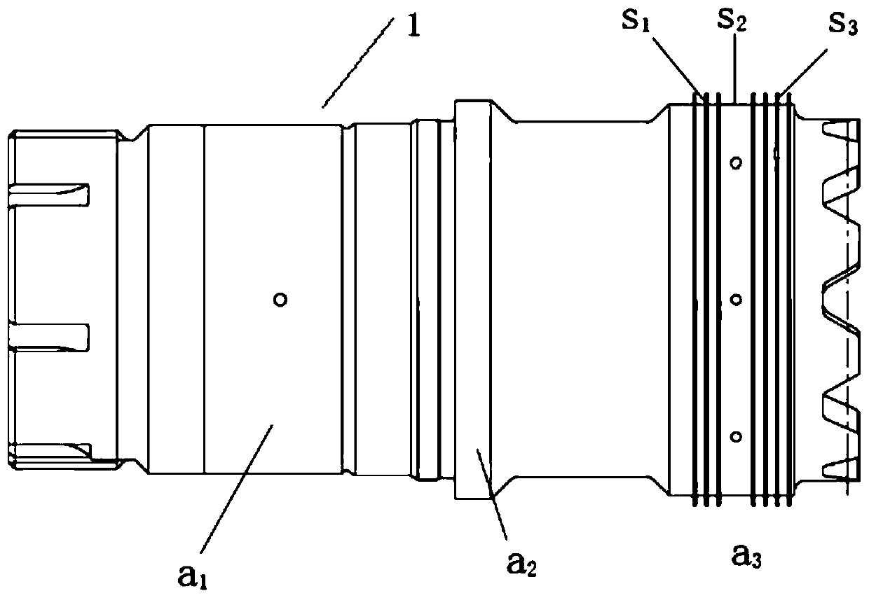
[0033] APS5000 Model APU Bearing Shaft Structure Introduction

[0034] figure 1 It is a schematic diagram of the structure of the APS5000 model APU bearing shaft. The main differences between the short shaft structure and common shafts are as follows: 1. Single tooth connection. 2. Large quality and small volume. 3. There is only one location for balanced materia...


PUM


Abstract

The invention discloses a method for controlling unbalance of an APU rotor assembly. The APU rotor assembly adopts a single-key tooth bearing shaft. The control method comprises a step of independently balancing the bearing shaft, specifically, the bearing shaft is subjected to weight reduction and placed on two supporting points of a balancing machine, the two supporting points are close to two ends of the bearing shaft respectively for supporting, the gravity center of the bearing shaft is made to be located between the two supporting points, and then the static unbalance amount of the bearing shaft is measured and adjusted through the balancing machine in a double-point supporting and middle ring belt rotating mode. The method for measuring the unbalance amount of the single-key gear shaft is advantaged in that measurement of the unbalance amount of the single-key gear shaft becomes possible from impossibility, so the bearing shaft is independently balanced before the overall balance of the rotor assembly, the overall balance quality of the APU rotor assembly is ensured by limiting the unbalance amount of the bearing shaft, and the smooth operation of the overall balance is ensured.

Description

technical field [0001] The invention relates to a method for controlling the unbalanced quantity of an aircraft APU rotor assembly. Background technique [0002] APU is the abbreviation of Aircraft Auxiliary Power Unit. The auxiliary power unit is a power unit on the aircraft except the main engine. The English name is Auxiliary Power Unit, referred to as APU. The last important and indispensable system is the device with the most complex structure and the highest precision on the aircraft except the main engine. [0003] As the most important core component in the APU, the rotor is the core for the APU to complete its intended functions. In a working environment with a rated speed of up to 50,000 revolutions per minute, the overall unbalance of the rotor assembly (there will be 5 to 8 rotor parts in an APU, and the rotor assembly is assembled from rotor parts) has always been an important indicator of APU performance . [0004] As a part of the rotor assembly, the beari...

Claims


Application Information

Patent Timeline
Patent Type & Authority Applications(China)
IPC IPC(8): G01M1/36G01M1/16
CPCG01M1/36G01M1/16
Inventor 王璐璐董仲伸徐长青
Owner 中国南方航空股份有限公司
Why Eureka
Try Eureka