

Positioning data generation method and device, and electronic equipment
A technology for locating data and data, which is applied in measurement devices, image data processing, and re-radiation of electromagnetic waves, which can solve problems such as unfavorable storage utilization and large amount of positioning data.
- Summary
- Abstract
- Description
- Claims
- Application Information
AI Technical Summary
Problems solved by technology
Method used
Image

Examples
Embodiment 1
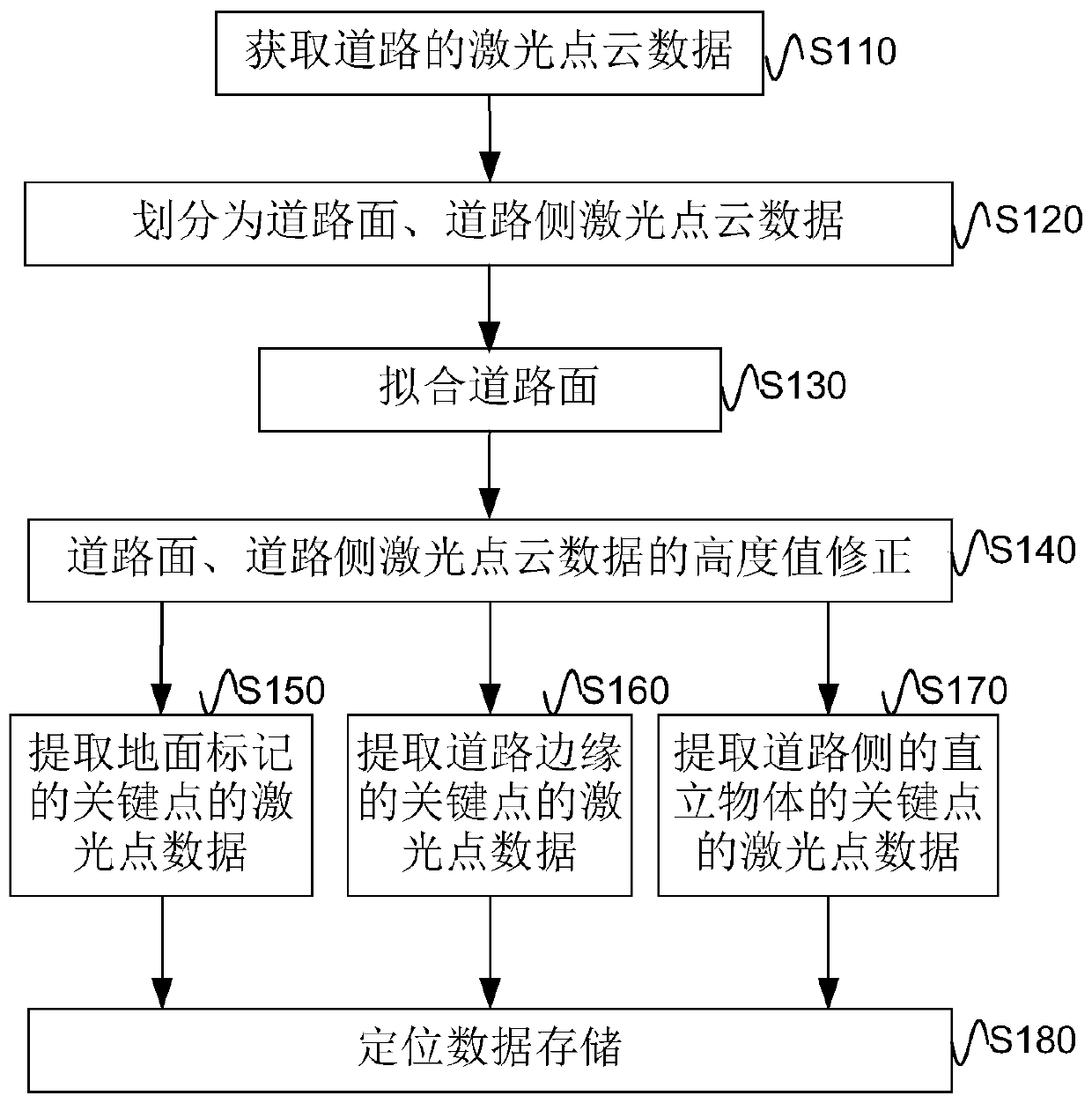
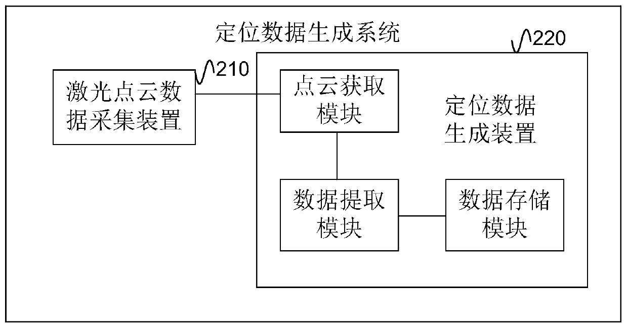
[0072] The idea of the solution based on the above positioning data generation, such as Figure 3a As shown in FIG. 1 , it is the first flow chart of the method for generating positioning data shown in the embodiment of the present invention, and the execution subject of the method may be figure 2 The positioning data generating means 220 shown in . Such as Figure 3a As shown, the positioning data generation method includes the following steps:
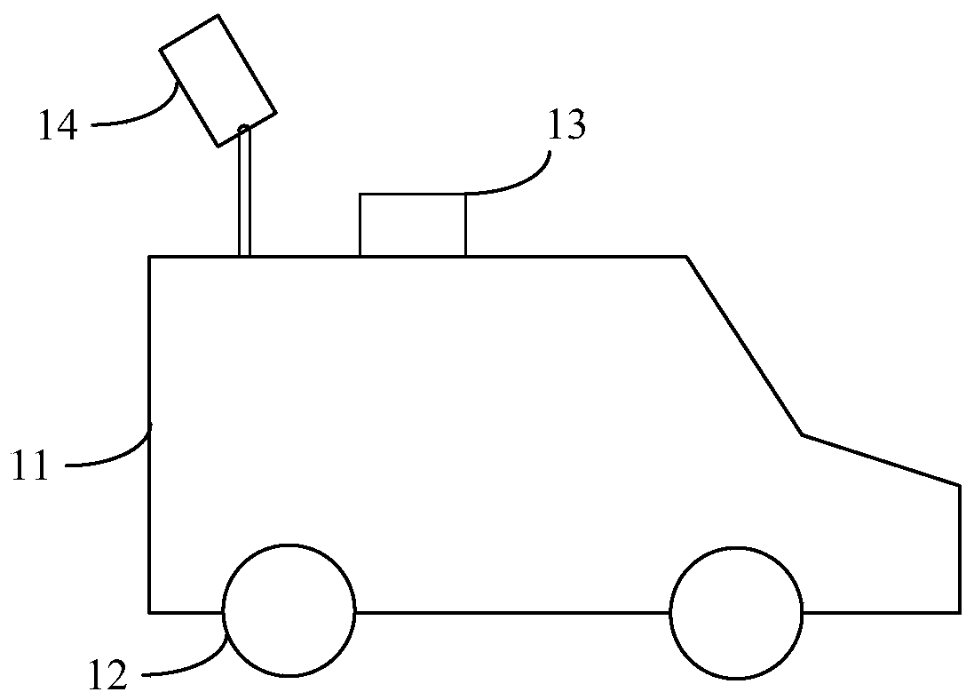
[0073] S310, acquiring laser point cloud data within a preset area of the road and / or both sides of the road.
[0074] From the laser point cloud data collected by the above laser point cloud data collection device 210, the laser point cloud data of the road and / or within the preset area on both sides of the road are obtained.
[0075] It should be noted that the laser point cloud at a very far position (tens of meters to hundreds of meters) can be obtained by actually scanning the laser radar. The accuracy of the laser point...
Embodiment 2
[0083] Such as Figure 4a As shown, it is the process flow of the positioning data generation method in the embodiment of the present invention Figure II . This embodiment and Figure 3a The difference of the shown methods is that this embodiment adopts a preferred implementation of extracting laser point data of key points of the road and / or target objects on both sides of the road from the laser point cloud data. Such as Figure 4a As shown, after step S310 in this embodiment, the following steps are performed:
[0084] S410, dividing the laser point cloud data into road surface laser point cloud data and / or road side laser point cloud data.
[0085] Specifically, the laser point cloud data within the above-mentioned preset area is divided into road surface laser point cloud data and / or road side (including road Left and right) Laser point cloud data.
[0086] In the actual application scenario, the height mutation points of the laser point cloud are found from each l...
Embodiment 3
[0104] Such as Figure 6 As shown, it is the fourth flowchart of the method for generating positioning data according to the embodiment of the present invention. This embodiment and Figure 4a The difference of the shown method is that this embodiment adopts a preferred implementation of extracting the laser point data of the key points of the target object of the road from the laser point cloud data of the road surface when the target object is a ground mark on the road. Such as Figure 6 As shown, after step S310 in this embodiment, the following steps are performed:
[0105] S411. Divide the laser point cloud data into road surface laser point cloud data.
[0106] This step may be a specific division method of dividing the laser point cloud data in step S410.
[0107] S610. Divide the road surface laser point cloud data into grids according to the preset grid size.
[0108] Wherein, the preset grid can be a two-dimensional grid set on the horizontal plane, and all road...
PUM
 Abstract
Description
Claims
Application Information