Intelligent watch control method

A control method, smart watch technology, applied to clocks, electronic timers, instruments, etc., can solve problems such as unfavorable memory operation, waterproof performance degradation, and a large amount of time spent

Active Publication Date: 2020-05-19
江西建南科技有限公司
View PDF10 Cites 4 Cited by
  • Summary
  • Abstract
  • Description
  • Claims
  • Application Information

AI Technical Summary

Problems solved by technology

However, it also brings new problems, such as too many buttons, which is not conducive to conventional memory operations, and users need to spend a lot of time to remember the function of each button; or, for structural design, every Adding a button will inevitably reduce the waterproof performance

Method used


Image

  • Intelligent watch control method
  • Intelligent watch control method
  • Intelligent watch control method

Examples


Embodiment 1

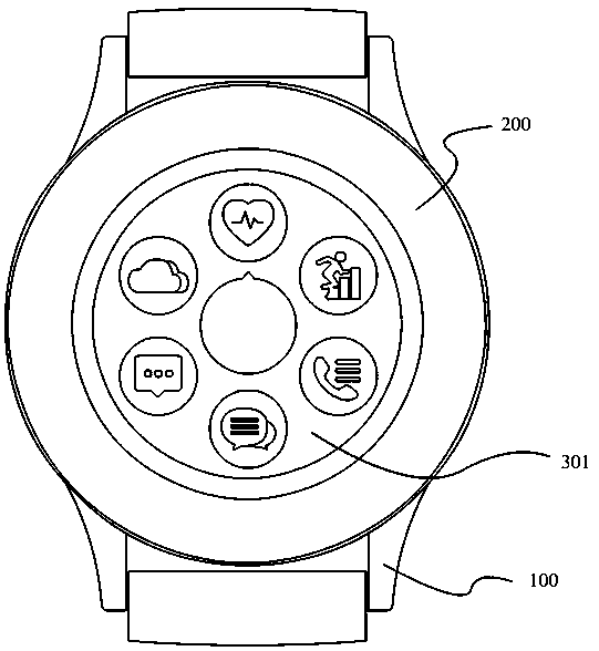
[0053] as attached figure 1 As shown, set a watch selection bit, if attached figure 1 The icon at 12 o'clock in the icon is the selected position, and the heart rate monitoring icon is in the selected position at this time, indicating that at this time, the heart rate monitoring operation step is entered.

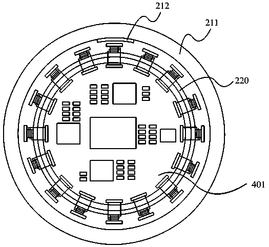
[0054] When other functions need to be selected, such as reading short messages, the processor on the main board 401 judges the direction of the generated current and the speed of the number of generated currents.

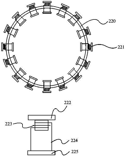
[0055] as attached figure 2 As shown, there are preferably 16 individual coil modules 221. If the first generation of current is each individual coil module 221 in the direction of 12 o'clock, then each individual coil module 221 on the left side of each individual coil module 221 generates current. a single coil module 221, then it is judged that the direction of the generated current is counterclockwise, and at this time, the processor makes the entire atta...

Embodiment 2

[0058] attached figure 1 The page selected for a function of the display screen 301, in fact, there are other pages that slide up and down like a mobile phone (such as the setting page of a general Android mobile phone).

[0059] As in Example 1, set a selected position. If the item to be selected is above the selected position, the screen needs to be pulled down. At this time, corresponding to the direction of the current, we can define the clockwise direction as pulling the screen down. direction, the counterclockwise direction is the direction to slide the screen up.

[0060] Similarly, the processor judges the direction and speed of the current generated in the single coil module 221. If the direction of the current is clockwise, the screen is pulled down. The speed of the pull-down depends on the speed at which the user rotates the outer shadow circle 211 of the watch.

Embodiment 3

[0062] More intuitively, it is time adjustment. Like Embodiment 1 and Embodiment 2, during the time adjustment operation, the outer shadow circle of the watch can be rotated, and the processor judges the direction and speed of the outer shadow circle rotation, thereby determining the time adjustment. direction and speed.

[0063] Through the above technical solution, the present invention removes the crown of the handle, and through the unique structural design, the outer shadow circle of the watch can have the same function as the crown.


PUM


Abstract

The invention relates to a control method of a intelligent watch. The method comprises the following steps: setting a selected position on a display screen; recording the position and sequence of a plurality of single coil modules which are uniformly fixed on the mainboard and arranged in a circle; the watch outer shadow ring is rotationally located on the outer rings of the multiple single coil modules arranged in the circular shape, a first magnet is arranged on the watch outer shadow ring, and when the watch outer shadow ring rotates, currents can be generated in the single coil modules opposite to the first magnet; judging the sequence and the speed of the current generated by the plurality of single coil modules, reading the mapping of the preset sequence and the preset speed of the current generated by the current page of the display screen and the change of the page, and adjusting the current page of the display screen; and judging the content at the selected position, and executing corresponding operation.

Description

technical field [0001] The invention relates to a control method for switching display interfaces of a smart watch. Background technique [0002] Due to the small number of physical buttons (commonly known as crown or handle) on smart watches, when defining the actions of the buttons, there are mainly actions such as single press, double press, triple press, left rotation, right rotation, etc. There are not many functions that can be defined . For smart watches that integrate more and more sensors and give more functions to the watch, since the touch screen is much smaller than that of the mobile phone and the operation of the screen is not so convenient, the current common use is to use three crowns. Or six crowns, which are defined separately by adding physical buttons. However, it also brings new problems, such as too many buttons, which is not conducive to conventional memory operations, and users need to spend a lot of time to remember the function of each button; or,...

Claims


Application Information

Patent Timeline
Patent Type & Authority Applications(China)
IPC IPC(8): G04G9/00G04G17/08G04G17/04
CPCG04G9/0064G04G17/04G04G17/045G04G17/08
Inventor 钟达
Owner 江西建南科技有限公司
Why Eureka
Try Eureka