
Device and method for preventing winding deformation of spiral copper pipe coil

A copper tube and coil technology, used in coil manufacturing, inductance/transformer/magnet manufacturing, electrical components, etc., can solve the problems of inconsistent spacing, unstable inductance value of copper tubes, flattening of copper tubes, etc., to achieve the effect of improving quality

Active Publication Date: 2020-05-19
深圳市高郭氏精密机械有限公司
View PDF10 Cites 2 Cited by
  • Summary
  • Abstract
  • Description
  • Claims
  • Application Information

AI Technical Summary

Problems solved by technology

[0004] The above existing technical solutions have the following defects: the opening of the copper pipe winding guide groove is set, so that there is enough deformation space for the copper pipe to wind along the copper pipe winding guide groove. The inner diameter and outer diameter of the copper tube itself will also undergo relatively large changes due to the overall bending deformation, which will cause the copper tube to become partially flattened, and the local flattening of the copper tube will easily lead to the winding of the copper tube. The distance between two adjacent circles on the top is inconsistent, which makes the inductance value of the wound copper tube unstable, so it needs to be improved

Method used


Image

  • Device and method for preventing winding deformation of spiral copper pipe coil
  • Device and method for preventing winding deformation of spiral copper pipe coil
  • Device and method for preventing winding deformation of spiral copper pipe coil

Examples


Embodiment 2

[0046] Embodiment two, refer to figure 1 and figure 2 , a method of use proposed based on the above-mentioned device for preventing the winding deformation of the spiral copper tube coil, which includes:

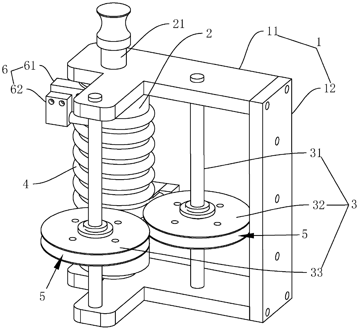
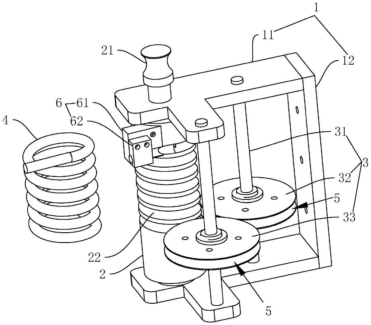
[0047] S1. First fix the bracket 1 on a workbench, and then fix one end of the cut copper tube to one end of the spiral groove 22 on the winding reel 2 through the starting clamp 6, and the deformation follows the wheel 32 and the setting follower wheel 33 all press the copper tube in the spiral groove 22 by the limiting groove 5 at the starting position of the copper tube bending.

[0048] S2. Rotate the winding reel 2 around the axis of the winding reel 2, so that the copper pipe is wound into the copper pipe coil 4 along the spiral groove 22, and finally the terminal end of the copper pipe is fixed on the termination clamp 6; After the tube coil 4 is formed, keep the copper tube coil 4 in the state on the winding reel 2 for at least two minutes, which can be two minute...

Embodiment 3

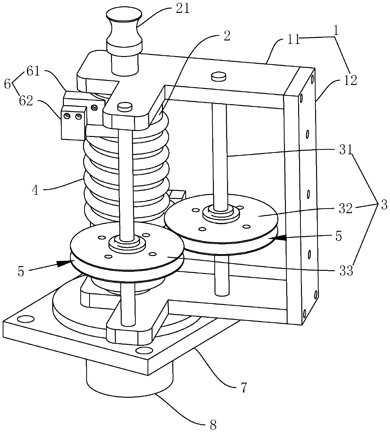
[0050] Embodiment three, refer to image 3 , Compared with Embodiment 1 and Embodiment 2, in Embodiment 3, a base 7 is also fixed by bolts at one end of the bracket 1. The base 7 is in the shape of a cuboid and is made of stainless steel. The round hole through which the connecting shaft 21 on the same side passes; the driver 8 for driving the winding reel 2 to rotate around its own axis is also fixed by screws on the base 7, the driver 8 is a servo motor, and the output shaft of the driver 8 It is connected with the connecting shaft 21 through a coupling, so that the driving member 8 can drive the connecting shaft 21 to rotate around its own axis.

Embodiment 4

[0051] Embodiment four, with reference to Figure 4 Compared with the third embodiment, the fourth embodiment is provided with a socket 211 for inserting other tools to rotate the winding reel 2 on a connecting shaft 21 away from the driving member 8 on the winding reel 2. At this time, the operation A person can insert a tool similar to a round rod into the insertion hole 211, and then turn the tool to achieve the purpose of driving the winding reel 2 to rotate around its own axis.


PUM


Abstract

The invention relates to a device for preventing winding deformation of a spiral copper pipe coil. The device comprises a support, a winding drum rotationally arranged on the support and used for winding a copper pipe coil, and a shaping grooved pulley group movably arranged on the support and used for assisting the shaping of a copper pipe. A spiral groove is formed in the axial side surface of the winding drum, and the copper pipe is wound along the spiral groove; a limiting groove is formed in the shaping grooved pulley group; a groove opening of the limiting groove is opposite to a grooveopening of the spiral groove; and the section of the limiting groove and the section of the spiral groove form a complete circle with the diameter equal to the outer diameter of the copper pipe. The device has the effects that the variation of the inner diameter and the outer diameter during winding of the copper pipe is reduced, the variation of the distance between every two adjacent circles ofthe copper pipe coil is reduced, and the inductance value of the copper pipe coil is more stable.

Description

technical field [0001] The invention relates to the technical field of copper pipe coil winding, in particular to a device and method for preventing deformation of spiral copper pipe coil winding. Background technique [0002] The coil winding used in the heating furnace is one of the important parts in the heating furnace. The coil winding is formed by winding copper pipe wire into a coil. [0003] In the prior art, a Chinese patent with authorized announcement number CN202601415U discloses a large-scale spiral copper tube coil forward and reverse winding device, which includes: forward and reverse reducer, reel, copper tube winding guide groove , Reel bearing; when winding copper tubes, first fix one end of the copper tube on the reel, turn on the forward and reverse reducer to make the reel bearing and the reel rotate around their own axis, and the copper tube is along the side surface of the reel shaft The copper tube winding guide groove on the top starts to wind forwa...

Claims


Application Information

Patent Timeline
Patent Type & Authority Applications(China)
IPC IPC(8): H01F41/06H01F41/082
CPCH01F41/06H01F41/082
Inventor 王永红
Owner 深圳市高郭氏精密机械有限公司
Learn More