A method for pushing vertically arranged optical disk arrays

A vertical arrangement, optical disc technology, applied in recording information storage, instruments and other directions, can solve the problems of optical disc damage, disc vertical jump, left and right shaking, etc., to improve safety, reduce the probability of collision, reduce the effect of inclination

Active Publication Date: 2021-09-07
江门晶铠信息科技有限公司
View PDF6 Cites 0 Cited by
  • Summary
  • Abstract
  • Description
  • Claims
  • Application Information

AI Technical Summary

Problems solved by technology

However, there are generally deficiencies in the existing many types of optical disc libraries, such as the large space occupied by the disk picking robot, which leads to the problem that the overall optical disc library occupies a large space, and in the process of accessing optical discs, due to the design of the equipment, the movement of the optical discs The problem of not smooth and not smooth
When the optical disc library is working, the optical disc needs to be read and written between the storage device of the optical disc library and the optical drive. The unsmooth movement of the optical disc will often cause the optical disc to jump vertically or shake from side to side, which undoubtedly increases the The probability of the disc colliding with the device, and even the disc is easily thrown out of the optical storage device due to the influence of external force
Once a disc collides or is thrown out of the optical storage device, it will inevitably cause irreversible damage to the disc, leading to data disasters and immeasurable losses
These design deficiencies are likely to lead to serious consequences, which should not be underestimated

Method used


Image

  • A method for pushing vertically arranged optical disk arrays
  • A method for pushing vertically arranged optical disk arrays
  • A method for pushing vertically arranged optical disk arrays

Examples


Embodiment

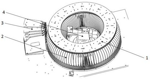
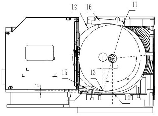
[0036] figure 1 It is a schematic diagram of the optical disc library of the present invention. As shown in the figure, this embodiment provides a method for pushing a vertically arranged optical disc array. A plurality of optical discs 2 are vertically arranged to form an optical disc storage array. The centers of the optical discs 2 are on the same horizontal plane On the outer side of the optical disc storage array, there is a vertically arranged read / write device 3, and the inner side is provided with a pushing device 4 that pushes the optical disc 2 into the read / write device 3, and a certain push force is pushed inside by a horizontal thrust. The optical disc 2 is used to move the pushed optical disc 2 toward the outside; the pushed optical disc 2 enters the read / write device 3 from the initial position along an inclined upward trajectory under the action of the thrust; the horizontal position of the thrust is higher than the optical disc 2 The horizontal plane where the...


PUM

PropertyMeasurementUnit
heightaaaaaaaaaa

Abstract

The present invention relates to the technical field of optical storage devices, and more specifically, to a method for pushing a vertically arranged optical disc array, comprising: a plurality of optical discs are vertically arranged to form an optical disc storage array, the centers of the optical discs are on the same horizontal plane, and the optical discs The outer side of the storage array is provided with a vertically arranged read / write device, and the inner side is provided with a pushing device for pushing the optical disc into the read / write device. It is characterized in that a certain optical disc is pushed inside by a thrust in the horizontal direction, so that The pushed optical disk moves outward; the pushed optical disk enters the read / write device from the initial position along an inclined upward trajectory under the action of the thrust; the horizontal position of the thrust is higher than the horizontal plane where the center of the optical disk is located, and is After the part of the pushed disc enters the read / write device and before canceling the pushing force, the center of the pushed disc is kept lower than the horizontal position of the pushing force. The invention can keep the optical disk smooth and stable during the movement.

Description

technical field [0001] The present invention relates to the technical field of optical storage devices, and more particularly, to a method for pushing a vertically arranged optical disc array. Background technique [0002] With the digitization of information resources and the rapid growth of information volume, the requirements for storage density, access speed and storage life of memory are constantly increasing. Optical storage, which can store data safely, at low cost, and for a long time, is gradually favored by people. Compared with the high price, complicated maintenance and high environmental requirements of hard disk storage, the cost of CD storage is lower, and the stored data is more secure and stable. Because the use of optical disk storage does not require continuous rotation like hard disks, the energy consumption is lower, and because the structure of the optical disk itself also determines that its service life is longer than that of hard disks, it can be us...

Claims


Application Information

Patent Timeline
Patent Type & Authority Patents(China)
IPC IPC(8): G11B17/24
CPCG11B17/24
Inventor 郑穆钟国裕
Owner 江门晶铠信息科技有限公司
Why Eureka
Try Eureka