Shield sealing structure of external current transformer in GIS
A technology of current transformer and sealing structure, applied in the direction of inductor, transformer/inductor shell, transformer/inductor parts, etc. The effect of the sealing effect
- Summary
- Abstract
- Description
- Claims
- Application Information
AI Technical Summary
Problems solved by technology
Method used
Image
Examples
specific Embodiment 1
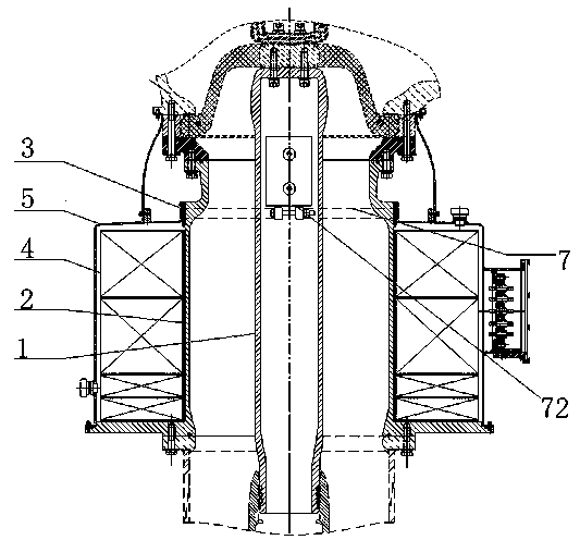
[0042] Such as Figure 2 to Figure 4 As shown, the shield sealing structure of the external current transformer in the GIS of the present invention includes a support cylinder 2 , a coil shield 5 , and an annular gasket 3 arranged between the support cylinder 2 and the coil shield 5 .
[0043] The supporting cylinder 2 is for the corresponding central conductor 1 in the GIS to pass through, and the transformer coil 4 is sleeved on its outside. The outer peripheral surface of the supporting cylinder 2 is provided with an annular boss 21, and one end of the annular gasket 3 is along the supporting cylinder. 2 is axially positioned on the annular boss 21. A coil shield 5 is provided on the outer cover of the transformer coil 4, and the coil shield 5 is used to protect the coil.
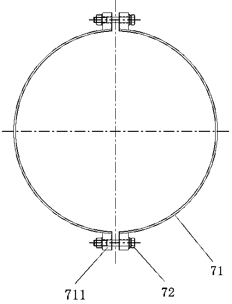
[0044]The coil shield 5 includes two shield bodies, the cross-section of the shield body is semi-circular, and the two sides of each shield body are provided with flange edges, and the bolt fasteners pa...
specific Embodiment 2
[0050] In Embodiment 1, the coil shield consists of two shield bodies. The difference between this embodiment and Embodiment 1 is that the coil shield is integrally formed with a thin-walled structure, and the thin-walled structure has certain shrinkability, so that The vertical folds on it can be tightened radially.
specific Embodiment 3
[0052] In Embodiment 1, the vertical flange is semi-circular, and the annular gasket is compressed by pressing the vertical flange with the ring hoop. The difference between this embodiment and Embodiment 1 is that the vertical flange is curved. Less than π / 2 arc-shaped vertical flange, and no deformation groove is set on it, but formed by the interval between two adjacent vertical flanges, ear plates are provided on the vertical flanges, and the bolts are fastened The vertical flange shrinks when the piece passes through the corresponding two ear plates, and then the annular gasket is compressed.
PUM
 Abstract
Description
Claims
Application Information
 - R&D
- Intellectual Property
- Life Sciences
- Materials
- Tech Scout
- Unparalleled Data Quality
- Higher Quality Content
- 60% Fewer Hallucinations
Browse by: Latest US Patents, China's latest patents, Technical Efficacy Thesaurus, Application Domain, Technology Topic, Popular Technical Reports.
© 2025 PatSnap. All rights reserved.Legal|Privacy policy|Modern Slavery Act Transparency Statement|Sitemap|About US| Contact US: help@patsnap.com


