water irrigation device
An irrigation device and water conservancy technology, applied in watering devices, gardening, agriculture, etc., can solve problems such as blockage and troublesome maintenance, and achieve the effect of reducing the number of pipes and improving the irrigation water rate.
- Summary
- Abstract
- Description
- Claims
- Application Information
AI Technical Summary
Problems solved by technology
Method used
Image
Examples
Embodiment 1
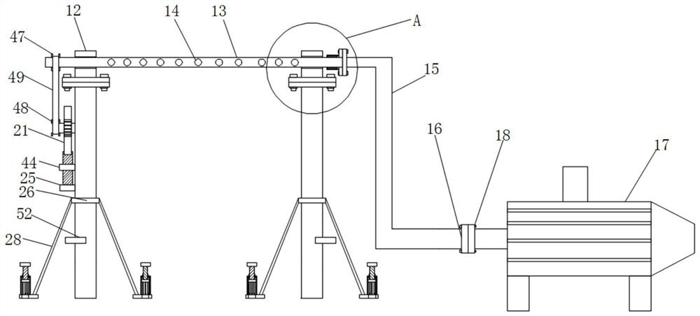
[0035] see Figure 1-10 , a water conservancy irrigation device according to an embodiment of the present invention, comprising two support columns 1, a cavity 2 is opened at the bottom of the support column 1, and a movable block 3 is arranged inside the cavity 2, The movable block one 3 is matched with the cavity 2, a limit mechanism is connected between the two sides of the movable block one 3 and the support column 1, and the bottom of the movable block one 3 is fixedly connected with a movable rod 4. The bottom of the movable rod 4 is fixedly connected with the movable block 2 5, the movable block 2 5 is matched with the cavity 2, the inner wall of the cavity 2 is fixedly connected with the limiting ring 6, and the limiting Ring 6 is positioned at the top of described movable block two 5, and limit ring 6 plays the effect of limit movable block one 3, makes movable block one 3 unable to break away from cavity 2 inside, and described limit ring 6 and described movable bloc...
Embodiment 2
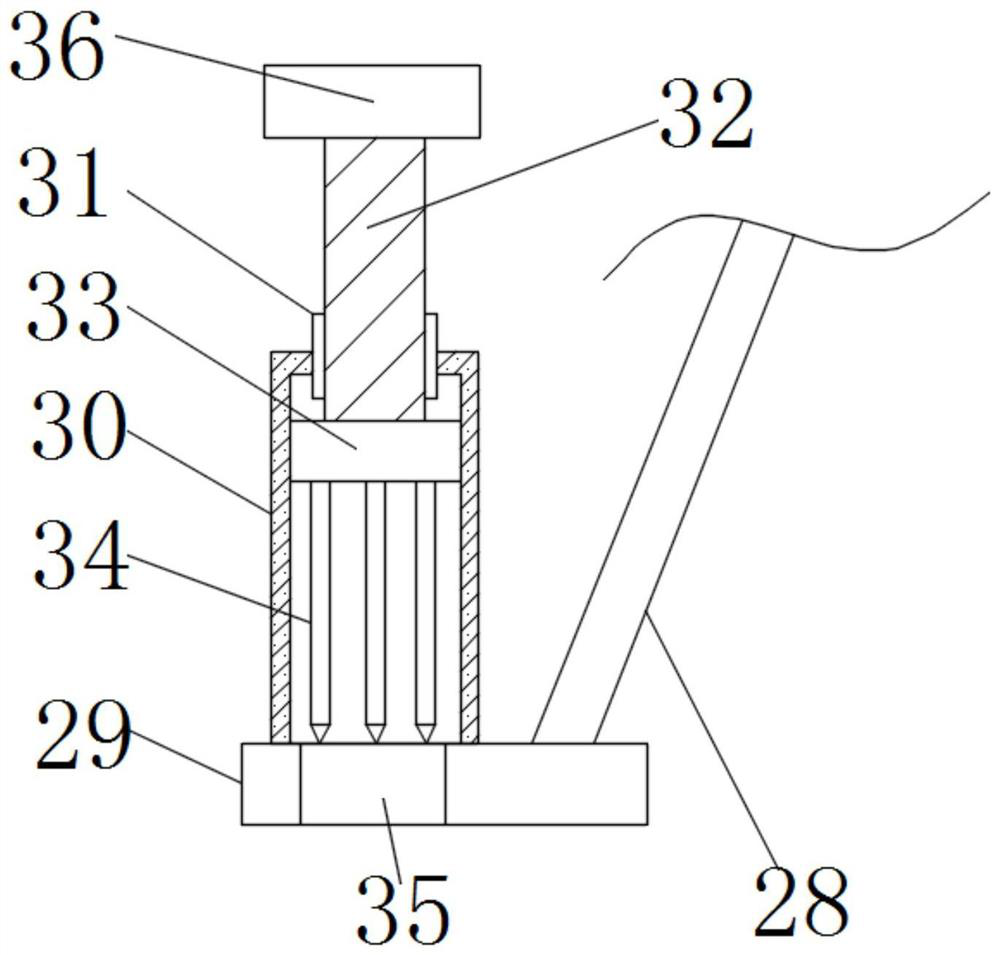
[0040] see image 3 , the insertion mechanism includes a sleeve 30, a threaded sleeve 31, a screw 32, a movable block three 33, an insertion rod 34 and a through hole 35, the top of the stable plate 29 is fixedly connected with a sleeve 30, and the sleeve 30 The top is fixedly connected with a threaded sleeve 31, and the internal thread of the threaded sleeve 31 is connected with a screw rod 32, and the bottom end of the screw rod 32 is positioned at the outside of the threaded sleeve 31 and is movably connected with the movable block three 33, and the screw rod 32 can pass through the bearing It is movably connected with the movable block three 33, and the bearing is embedded in the top of the movable block three 33, and the screw rod 32 is connected with the inner wall of the bearing. The movable block three 33 is matched with the inner wall of the sleeve 30, and the movable block three 33 The bottom is fixedly connected with a plurality of insertion rods 34. The bottom of t...
Embodiment 3
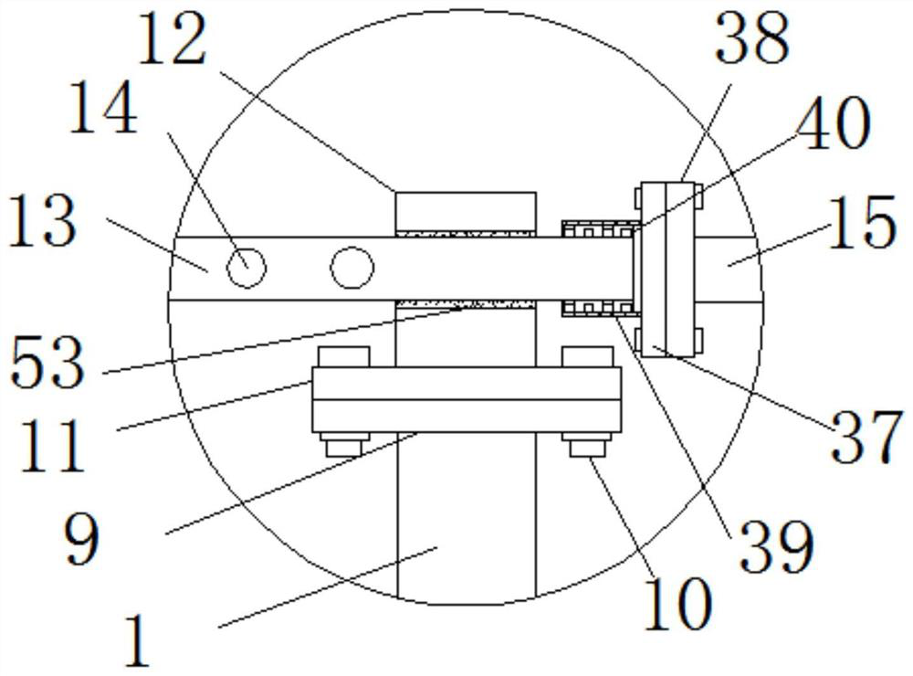
[0042] see figure 2 , the connecting mechanism includes a connecting flange one 37, a connecting flange two 38, a connecting sleeve 39 and a bearing one 40, the outer surface of one end of the movable pipe 13 close to the water pipe 15 is connected with a bearing one 40, and the bearing one The outer surface of 40 is fixedly connected with a connection sleeve 39, the port of the connection sleeve 39 is fixedly connected with a connection flange 1 37, and the end of the water pipe 15 close to the movable pipe 13 is connected with a connection flange 2 38, the connection The first flange 37 and the second connecting flange 38 are connected by bolts, and the connecting mechanism can connect the port of the movable pipe 13 to the water pipe 15 , and the rotation of the movable pipe 13 will not affect the water pipe 15 .
PUM
 Abstract
Description
Claims
Application Information
 - R&D
- Intellectual Property
- Life Sciences
- Materials
- Tech Scout
- Unparalleled Data Quality
- Higher Quality Content
- 60% Fewer Hallucinations
Browse by: Latest US Patents, China's latest patents, Technical Efficacy Thesaurus, Application Domain, Technology Topic, Popular Technical Reports.
© 2025 PatSnap. All rights reserved.Legal|Privacy policy|Modern Slavery Act Transparency Statement|Sitemap|About US| Contact US: help@patsnap.com


