Valve, method for diagnosing abnormality of valve, and computer program

A computer program, abnormal diagnosis technology, applied in the field of valve, valve abnormal diagnosis and computer program field, can solve problems such as complicated wiring

Inactive Publication Date: 2020-05-26
FUJIKIN INC
View PDF8 Cites 0 Cited by
  • Summary
  • Abstract
  • Description
  • Claims
  • Application Information

AI Technical Summary

Problems solved by technology

In addition, with the advancement of fluid control equipment, the wiring around the fluid control equipment, such as electrical wiring and air pipes for supplying driving pressure, is also complicated.

Method used


Image

  • Valve, method for diagnosing abnormality of valve, and computer program
  • Valve, method for diagnosing abnormality of valve, and computer program
  • Valve, method for diagnosing abnormality of valve, and computer program

Examples


Embodiment Construction

[0044] ●Valve V1

[0045] Hereinafter, the valve according to the embodiment of the present invention and a method for diagnosing abnormality of the valve will be described.

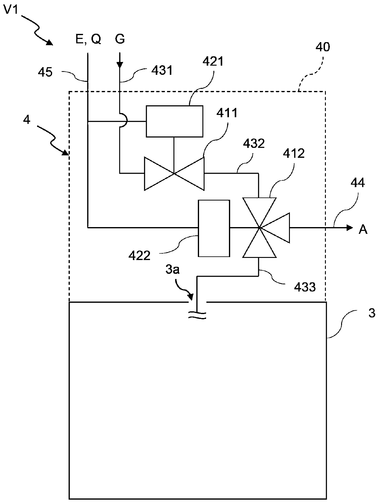
[0046] like figure 1 As shown, the valve V1 according to the present embodiment includes a valve body 3 and a driving pressure control device 4 connected to the valve body 3 .

[0047] The valve body 3 is, for example, a valve used in a gas line of a fluid control device such as a diaphragm valve, and includes at least a driving pressure introduction port 3a for introducing driving pressure supplied from the outside to the inside.

[0048] The driving pressure control device 4 is connected to the driving pressure inlet port 3 a of the valve body 3 , and supplies the driving pressure supplied from the driving pressure supply source G to the valve body 3 .

[0049] The driving pressure control device 4 includes driving pressure introduction passages 431 , 432 , and 433 as introduction passages for introd...


PUM


Abstract

The invention can make it possible to correctly and simply diagnose operation abnormalities in a valve. A valve (V1) with which it is possible to detect operation abnormalities has: a magnet (M1) attached near a pressing adapter (52) of a stem (53) that slides in accordance with the opening and closing motion of the valve (V1); and a magnetic sensor (M2) attached to a surface facing the stem (53),the surface being the inner side of the pressing adapter (52) that presses the peripheral edge of a diaphragm (51), the magnetic sensor (M2) detecting changes in the distance from the magnet (M1). Furthermore, an abnormality determination means compares the change detected by the magnetic sensor (M2) in the distance between the magnet (M1) and the magnetic sensor (M2) during abnormality diagnosis, with the change in distance between the magnet (M1) and the magnetic sensor (M2) during normal operation as measured in advance, and determines the presence of abnormalities.

Description

technical field [0001] The present invention relates to a valve capable of abnormality diagnosis and a method for diagnosing the abnormality of the valve. Background technique [0002] A fluid control device such as an automatic valve is used in a fluid supply line for supplying a process fluid used in a semiconductor manufacturing process. [0003] In recent years, semiconductor manufacturing processes such as ALD (Atomic Layer Deposition; Atomic Layer Deposition) have advanced and become more complicated, and the number of fluid control devices mounted on gas modules has increased. In addition, as the fluid control equipment becomes more sophisticated, the wiring around the fluid control equipment, such as electrical wiring and air pipes for supplying driving pressure, becomes complicated. [0004] Regarding this point, Patent Document 1 proposes a valve comprising: a main body in which a first flow path and a second flow path are formed; connect or truncate. The main b...

Claims


Application Information

Patent Timeline
Patent Type & Authority Applications(China)
IPC IPC(8): F16K37/00F16K7/12
CPCG01M13/003F16K7/17F16K31/1226F16K37/0041F16K37/0033F16K7/16
Inventor 丹野龙太郎相川献治原田章弘铃木裕也松田隆博米华克典落石将彦篠原努
Owner FUJIKIN INC
Why Eureka
Try Eureka