Video monitoring device with wireless transmitter

A wireless transmitter, video monitoring technology, applied in supporting machines, closed-circuit television systems, mechanical equipment, etc., can solve the problems of large video space, low transmission efficiency, weak wireless signals, etc., to achieve simple and efficient connection, improve Transmission efficiency, the effect of reducing the influence of the transmission signal

Active Publication Date: 2020-05-29
九江思源软件有限公司
View PDF9 Cites 0 Cited by
  • Summary
  • Abstract
  • Description
  • Claims
  • Application Information

AI Technical Summary

Problems solved by technology

[0002] With the continuous development of monitoring equipment, video monitoring is widely used in all walks of life. For video monitoring equipment, currently, wired methods are generally used to transmit video data. However, for some remote areas, such as mountains, remote For the monitoring of roads, seashores, field construction, field forests and other occasions, if a special transmission signal line is set up, it will not only cost a lot, but also be very difficult to build.
For forests, mountains, wild places, etc., the wireless signal is generally weak, and because the video occupies a relatively large space, this leads to slow transmission and low transmission efficiency when ordinary wireless equipment is used for signal transmission. High, prone to problems such as signal interruption

Method used


Image

  • Video monitoring device with wireless transmitter
  • Video monitoring device with wireless transmitter
  • Video monitoring device with wireless transmitter

Examples


Embodiment Construction

[0024] The following will be combined with Figure 1-7 The present invention is described in detail, and the technical solutions in the embodiments of the present invention are clearly and completely described. Apparently, the described embodiments are only some of the embodiments of the present invention, not all of them. Based on the embodiments of the present invention, all other embodiments obtained by persons of ordinary skill in the art without making creative efforts belong to the protection scope of the present invention.

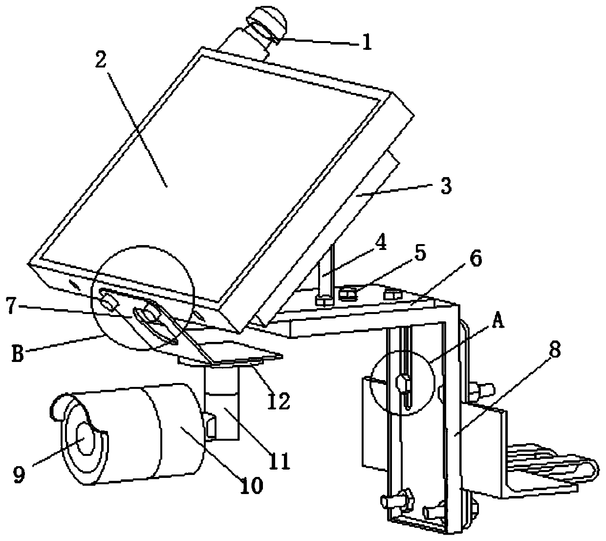
[0025] The present invention provides a kind of video monitoring device with wireless transmitter here through improvement, comprises video monitoring mechanism, fixed installation mechanism and wireless transmitting mechanism 1, and described video monitoring mechanism and described wireless transmitting mechanism can be installed in adjustable angle On the fixed installation mechanism, the video monitoring mechanism is connected with the wireless ...


PUM


Abstract

The invention discloses a video monitoring device with a wireless transmitter. A wireless transmitting mechanism is arranged to comprise a first wireless transmitter base of a cylindrical structure and a second wireless transmitter base of a cylindrical structure. A plurality of first wireless transmitters are arranged on the outer circumference of the first wireless transmitter seat in a circumferential array manner; a plurality of second wireless transmitters are arranged on the outer circumference of the second wireless transmitter seat in a circumferential array manner; each first wirelesstransmitter and each second wireless transmitter are in signal connection to the video monitoring mechanism in a parallel connection manner; thus, the transmission efficiency can be improved in a parallel mode; the first wireless transmitter seat and the second wireless transmitter seat are coaxially connected together; the first wireless transmitter seat and the second wireless transmitter seatare arranged on the base and are driven to rotate around the axis by a common driving mechanism, and the rotation rates of the first wireless transmitter seat and the second wireless transmitter seatare different, so that transmission can be realized at different azimuth angles, the transmission capability is improved, and the influence of an obstruction on a transmission signal is reduced.

Description

technical field [0001] The invention specifically relates to a video monitoring device with a wireless transmitter, and relates to the related field of monitoring applications. Background technique [0002] With the continuous development of monitoring equipment, video monitoring is widely used in all walks of life. For video monitoring equipment, currently, wired methods are generally used to transmit video data. However, for some remote areas, such as mountains, remote For the monitoring of roads, seashores, field construction, field forests and other occasions, if a special transmission signal line is set up, it will not only cost a lot, but also be very difficult to build. For forests, mountains, wild places, etc., the wireless signal is generally weak, and because the video occupies a relatively large space, this leads to slow transmission and low transmission efficiency when ordinary wireless equipment is used for signal transmission. High, prone to problems such as s...

Claims


Application Information

Patent Timeline
Patent Type & Authority Applications(China)
IPC IPC(8): H04N7/18F16M11/04F16M11/06F16M11/18F16M13/02
CPCF16M11/04F16M11/06F16M11/18F16M13/02H04N7/18
Inventor 李宗锋
Owner 九江思源软件有限公司
Why Eureka
Try Eureka