
Bending device for water pipe processing

A technology for a bending device and a water pipe, which is applied in the field of bending devices for water pipe processing, can solve the problems of water pipe bending, water pipe falling off, water pipe sliding, etc., and achieves the effect of preventing damage

Inactive Publication Date: 2020-06-02
广州迅磊科技有限公司
View PDF1 Cites 0 Cited by
  • Summary
  • Abstract
  • Description
  • Claims
  • Application Information

AI Technical Summary

Problems solved by technology

A steel pipe high-efficiency bending device in the above-mentioned patent has the following disadvantages: when the water pipe is bent, the water pipe is usually squeezed, but since the cross-section of the water pipe is circular, it may be bent due to The surface of the water pipe is relatively smooth, which causes the water pipe to slip, which in turn causes the water pipe to fall off the device and affects the bending of the water pipe

Method used


Image

  • Bending device for water pipe processing
  • Bending device for water pipe processing
  • Bending device for water pipe processing

Examples


Embodiment 1

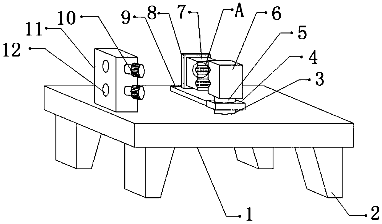
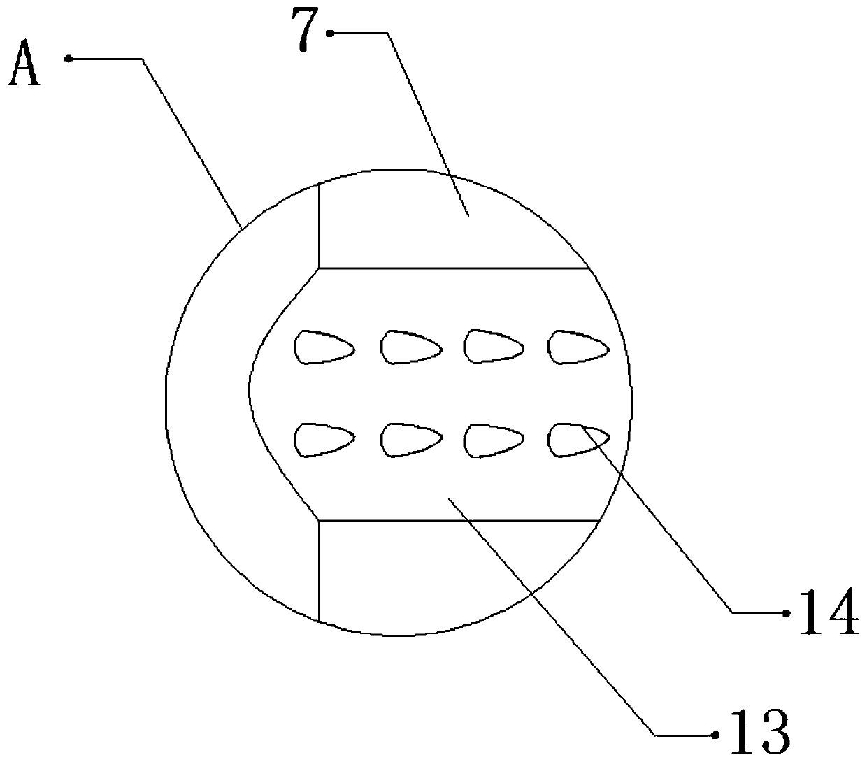
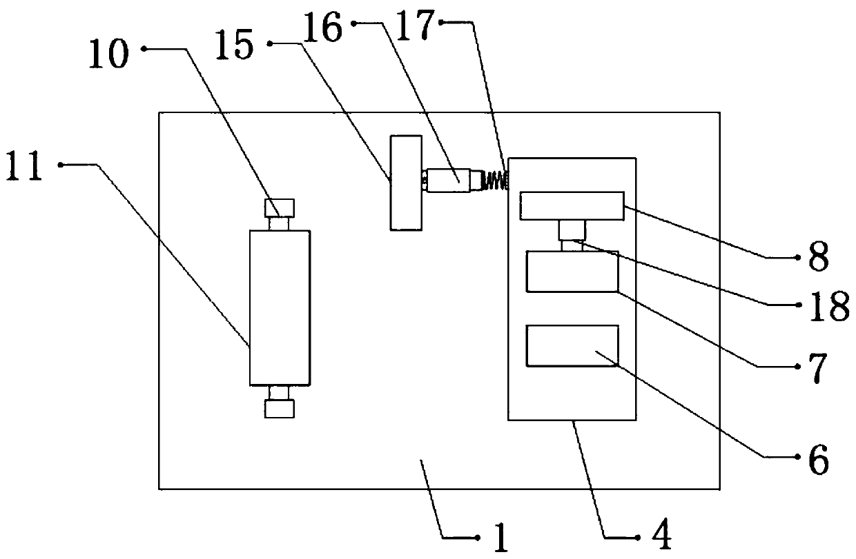
[0029] refer to Figure 1-4 , a bending device for water pipe processing, comprising a fixed seat 1, one side of the top outer wall of the fixed seat 1 is connected to a rotating shaft 3 through bearing rotation, and the top outer wall of the rotating shaft 3 is connected to a fixed block 4 by bolts, and the top of the fixed block 4 The outer wall is connected with a fixed shaft 5 by bolts, and the top outer wall of the fixed shaft 5 is connected with a bending mechanism 6 by bolts, and the outer wall of one side of the fixed block 4 is connected with a connecting plate 9 by bolts, and one side of the outer wall of the top of the connecting plate 9 passes through Bolts are connected with a support plate 8, and one side of the outer wall of the support plate 8 is connected with an electric telescopic rod 18 by bolts, and one side of the outer wall of the electric telescopic rod 18 is connected with a splint 7 by bolts, one side of the splint 7 and the bending mechanism 6 Limiti...

Embodiment 2

[0038] refer to Figure 5-6 , a bending device for water pipe processing. Compared with Embodiment 1, the outer walls of the opposite sides of the two restraining plates 19 are provided with a plurality of protruding teeth 20, and both the protruding teeth 20 and the constraining plates 19 are flexible. The material can cover the other end of the water pipe so as to protect the water pipe and prevent the surface of the water pipe from being damaged due to external force when the water pipe is bent. Slipping occurs inside.

[0039] Working principle: When in use, place the water pipe inside the limit groove 13 through the jack 12, start the electric telescopic rod 18, and the electric telescopic rod 18 will drive the splint 7 to move, so that the splint 7 can clamp and fix the water pipe, and pass The convex teeth 14 can increase the friction between the water pipe and the limiting groove 13, so as to fix the water pipe and prevent the water pipe from slipping from the device ...


PUM


Abstract

The invention discloses a bending device for water pipe processing. The bending device comprises a fixed seat, and one side of the outer wall of the top of the fixed seat is rotationally connected with a rotary shaft through a bearing. A fixed block is fixed to the outer wall of the top of the rotary shaft, and a fixed shaft is fixed to the outer wall of the top of the fixed block. A bending mechanism is fixed to the outer wall of the top of the fixed shaft, and a connecting plate is fixed to the outer wall of one side of the fixed block. A supporting plate is fixed to one side of the outer wall of the top of the connecting plate, and the outer wall of one side of the supporting plate is fixedly connected with an electric telescopic rod. A clamping plate is fixed to the outer wall of one side of the electric telescopic rod, and limiting grooves are formed in the outer wall of one side of the clamping plate and the outer wall of one side of the bending mechanism. According to the bending device, it can be avoided that when a water pipe is bent, due to the fact that the surface of the water pipe is smooth, the water pipe slides off from the device; it can be avoided that one end of the water pipe deviates to influence bending of the water pipe; and it can be avoided that when the water pipe is bent, due to external force, the surface of the water pipe is damaged.

Description

technical field [0001] The invention relates to the technical field of water pipe processing, in particular to a bending device for water pipe processing. Background technique [0002] Water pipes are water supply pipes. Modern decoration water pipes are constructed with buried walls, and some water pipes are made of metal. Therefore, when processing metal water pipes, the water pipes are usually bent by bending devices according to needs. . [0003] After searching, the Chinese patent authorization number is CN105772548B, which discloses a high-efficiency bending device for steel pipes. The technical problem to be solved by the present invention is to provide a high-efficiency steel pipe bending device with fast bending speed, good bending effect and simple operation. In order to solve the above technical problems, the present invention provides such a high-efficiency bending device for steel pipes, which includes a bottom plate, a cylinder I, an electric wheel, a pull wi...

Claims


Application Information

Patent Timeline
Patent Type & Authority Applications(China)
IPC IPC(8): B21D7/024
CPCB21D7/024
Inventor 夏波
Owner 广州迅磊科技有限公司
Learn More