Cutting workbench convenient to adjust

A workbench and workbench base technology, which is applied in the direction of manufacturing tools, metal sawing equipment, metal processing equipment, etc., can solve the problems of difficult adjustment, small application range, and low work efficiency, so as to improve work efficiency and increase the adjustment range , the effect of improving the degree of convenience

Inactive Publication Date: 2020-06-02
新沂经济开发区建设发展有限公司
View PDF0 Cites 1 Cited by
  • Summary
  • Abstract
  • Description
  • Claims
  • Application Information

AI Technical Summary

Problems solved by technology

[0002] In industrial production, with the development of science and technology, the industrial cutting machine table is an indispensable tool for industrial production, and in order to ensure the quality and efficiency of material cutting work, it is necessary to strengthen the improvement and optimization of cutting technology, in order to improve work efficiency While reducing costs, usually, during the cutting process of materials, the general industrial cutting machine table includes a simple structure such as a support plate, a drive motor, a saw blade, a cutting groove, and a bottom plate. During the use of a traditional cutting machine, the work The position of the table is fixed, it is not easy to adjust, the workbench is highly targeted, the scope of application is small, and the reaction to the technical and variability of the product is relatively slow, and most of the cutting machines are manually operated, with poor continuity and stability, which leads to work Low efficiency, not enough to meet the needs of the rapid development of modern industry

Method used


Image

  • Cutting workbench convenient to adjust
  • Cutting workbench convenient to adjust
  • Cutting workbench convenient to adjust

Examples


Embodiment Construction

[0016] The following will clearly and completely describe the technical solutions in the embodiments of the present invention with reference to the accompanying drawings in the embodiments of the present invention. Obviously, the described embodiments are only some, not all, embodiments of the present invention. Based on the embodiments of the present invention, all other embodiments obtained by persons of ordinary skill in the art without making creative efforts belong to the protection scope of the present invention.

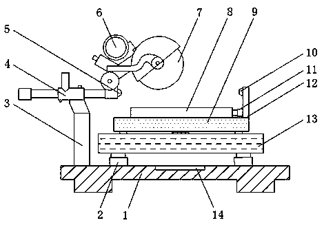
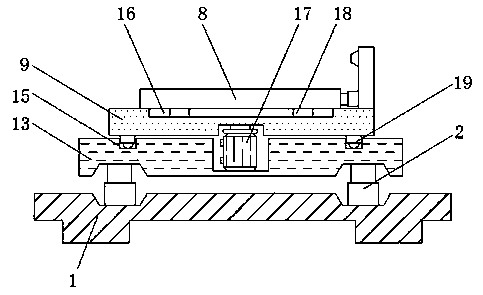
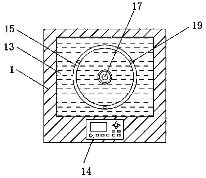
[0017] see Figure 1-3 , a kind of embodiment that the present invention provides: a kind of cutting workbench that is easy to adjust, comprises workbench base 1, vertical telescoping rod 2, stand 3, baffle plate 12 and lifting table 13, and the top end of workbench base 1 is fixed There are four vertical telescopic poles 2, and a lifting platform 13 is arranged above the vertical telescopic poles 2, and the bottom end of the lifting platform 13 is fixedly con...


PUM


Abstract

The invention discloses a cutting workbench convenient to adjust. The cutting workbench comprises a workbench base, vertical telescopic rods, a vertical frame, a baffle and a lifting table, wherein the four vertical telescopic rods are arranged at the top end of the workbench base; the lifting table is arranged above the vertical telescopic rods; the bottom end of the lifting table is fixedly connected with the output ends of the vertical telescopic rods; a main motor is arranged at the center position in the lifting table; the output end of the main motor is provided with a rotation shaft through a coupler; a rotation table is arranged above the lifting table; the bottom end of the rotation table is fixedly connected with the top end of the rotation shaft; an infrared receiver is arrangedon one side of the top end of the baffle; and the side, close to the lifting table, of a cross beam is provided with an infrared emitter, and the output end of the infrared emitter is electrically connected with the input end of the infrared receiver. According to the cutting workbench, the convenience degree during cutting platform adjusting usage is improved, the adjusting range of the workbench is enlarged, and the work efficiency of the workbench is greatly improved.

Description

technical field [0001] The invention relates to the technical field of material cutting, in particular to an easily adjustable cutting workbench. Background technique [0002] In industrial production, with the development of science and technology, the industrial cutting machine table is an indispensable tool for industrial production, and in order to ensure the quality and efficiency of material cutting work, it is necessary to strengthen the improvement and optimization of cutting technology, in order to improve work efficiency While reducing costs, usually, during the cutting process of materials, the general industrial cutting machine table includes a simple structure such as a support plate, a drive motor, a saw blade, a cutting groove, and a bottom plate. During the use of a traditional cutting machine, the work The position of the table is fixed, it is not easy to adjust, the workbench is highly targeted, the scope of application is small, and the reaction to the tec...

Claims


Application Information

Patent Timeline
Patent Type & Authority Applications(China)
IPC IPC(8): B23D47/02
CPCB23D47/025
Inventor 不公告发明人
Owner 新沂经济开发区建设发展有限公司
Why Eureka
Try Eureka