
Clamping device for hardware mold machining

A mold processing and clamping device technology, which is applied in metal processing equipment, metal processing machinery parts, positioning devices, etc., can solve the problem of mold lateral movement and achieve the effect that it will not move easily

Inactive Publication Date: 2020-06-02
YANGZHOU SITONG POWDER METALLURGY
View PDF0 Cites 6 Cited by
  • Summary
  • Abstract
  • Description
  • Claims
  • Application Information

AI Technical Summary

Problems solved by technology

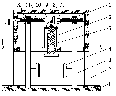
[0003] The purpose of this invention is to solve the problem in the prior art that the mold tends to move laterally when it is subjected to a large force, and proposes a clamping device for metal mold processing

Method used


Image

  • Clamping device for hardware mold machining
  • Clamping device for hardware mold machining
  • Clamping device for hardware mold machining

Examples


Embodiment Construction

[0020] The following will clearly and completely describe the technical solutions in the embodiments of the present invention with reference to the accompanying drawings in the embodiments of the present invention. Obviously, the described embodiments are only some, not all, embodiments of the present invention.

[0021] In describing the present invention, it should be understood that the terms "upper", "lower", "front", "rear", "left", "right", "top", "bottom", "inner", " The orientation or positional relationship indicated by "outside", etc. is based on the orientation or positional relationship shown in the drawings, and is only for the convenience of describing the present invention and simplifying the description, rather than indicating or implying that the referred device or element must have a specific orientation, so as to Specific orientation configurations and operations, therefore, are not to be construed as limitations on the invention.

[0022] refer to Figure ...


PUM


Abstract

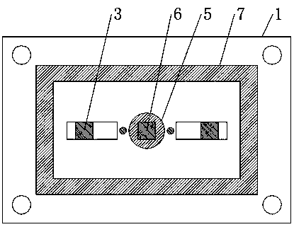
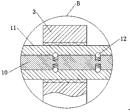
The invention discloses a clamping device for hardware mold machining. The clamping device comprises a bottom plate, supporting rods are correspondingly and fixedly installed at four corners of the top of the bottom plate, installation boxes are correspondingly and fixedly connected to the tops of the four supporting rods, hollow first screw rods and hollow second screw rods which are horizontallyarranged are arranged in the installation boxes, threads of the first screw rods and the second screw rods are opposite in screwing direction and same in screw pitch, the ends, away from each other,of the first screw rods and the second screw rods are correspondingly and rotatably connected to the inner walls of the installation boxes, a rotating rod is jointly arranged on the inner walls of thefirst screw rods and the second screw rods, one end of the rotating rod is rotatably connected with the inner walls of the installation boxes, the other end of the rotating rod penetrates and extendsto the outside of the installation boxes, and a plurality of first spring grooves which are uniformly distributed are formed in the side wall, located in the first screw rods and the second screw rods, of the rotating rod. According to the clamping device, a clamping plate is utilized to clamp a mold in three directions to achieve the purpose of clamping the mold stably and not easily moving.

Description

technical field [0001] The invention relates to the technical field of metal mold processing, in particular to a clamping device for metal mold processing. Background technique [0002] Metal molds are used in industrial production, using various presses and special tools installed on the presses. Before the mold is used, it is often necessary to process the mold, and it needs to be clamped when the mold is processed. Directly use the screw rod to squeeze the mold from top to bottom, so that the mold is clamped on the bottom plate, but this clamping method makes the mold tend to move laterally when it is subjected to a large force, thus increasing the operator's operation Difficulty, time-consuming and labor-intensive. Contents of the invention [0003] The purpose of the present invention is to solve the problem in the prior art that the mold tends to move laterally when it is subjected to a large force, and proposes a clamping device for metal mold processing. [0004]...

Claims


Application Information

Patent Timeline
Patent Type & Authority Applications(China)
IPC IPC(8): B23Q3/06
CPCB23Q3/062
Inventor 王晶
Owner YANGZHOU SITONG POWDER METALLURGY
Learn More