
New energy automobile with adjustable solar panel

A technology for new energy vehicles and solar panels, applied in the field of new energy vehicles, can solve the problems of satisfying the light intensity, inconvenient adjustment of the angle of the solar panels, reducing the utilization rate of solar energy, etc., and achieve the effects of satisfying the light intensity, simple structure and convenient operation.

Inactive Publication Date: 2020-06-02
张扬
View PDF2 Cites 0 Cited by
  • Summary
  • Abstract
  • Description
  • Claims
  • Application Information

AI Technical Summary

Problems solved by technology

[0006] The purpose of the present invention is to solve the disadvantages in the prior art that it is inconvenient to adjust the angle of the solar panel, cannot satisfy the maximum intensity of light, and reduces the utilization rate of solar energy, and proposes an adjustable solar panel new energy vehicles

Method used


Image

  • New energy automobile with adjustable solar panel
  • New energy automobile with adjustable solar panel
  • New energy automobile with adjustable solar panel

Examples


Embodiment 1

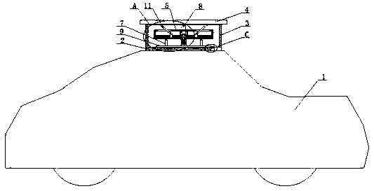
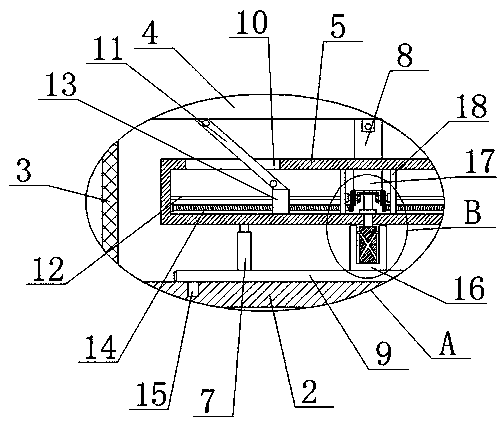
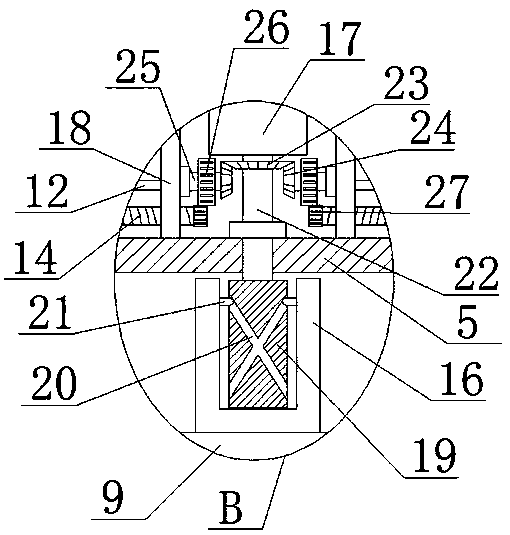
[0030] refer to Figure 1-6 , a new energy vehicle with adjustable solar panels, comprising a vehicle body 1, a solar panel 4 is arranged on the top of the vehicle body 1, the solar panel 4 is connected to a battery inside the vehicle body 1, and a support plate is fixedly connected to the top of the vehicle body 1 2. The top of the support plate 2 is rotatably connected with a rotating disk 9, and the top of the rotating disk 9 is fixedly connected with four telescopic support rods 7, and the tops of the four telescopic support rods 7 are fixedly connected with the same fixed box 5, and the telescopic support rods 7. Support the fixed box 5, the top of the fixed box 5 is fixedly connected with a support block 8, the bottom of the solar panel 4 is connected with the top of the support block 8 in rotation, the top of the support plate 2 is provided with a rotating mechanism, and the rotating mechanism and the rotating disk 9 Compatible with each other, the inner horizontal slid...

Embodiment 2

[0039] refer to Figure 1-6 , a new energy vehicle with adjustable solar panels, comprising a car body 1, a solar panel 4 is arranged on the top of the car body 1, the solar panel 4 is connected to a battery inside the car body 1, and the top of the car body 1 is fixedly connected with a Support plate 2, the top of support plate 2 is connected with rotating disk 9, the top of rotating disk 9 is fixedly connected with four telescopic support rods 7 by screws, and the tops of four telescopic support rods 7 are all fixedly connected with the same fixed rod by screws. Box 5, telescopic support rod 7 supports the fixed box 5, the top of the fixed box 5 is fixedly connected with a support block 8 by screws, the bottom of the solar panel 4 is rotationally connected with the top of the support block 8, and the top of the support plate 2 is provided with a rotating Mechanism, the rotating mechanism is adapted to the rotating disk 9, and the inner horizontal sliding connection of the fi...


PUM


Abstract

The invention belongs to the technical field of solar panel angle adjustment, and especially relates to a new energy automobile with an adjustable solar panel. In the prior art, the angle of a solar panel is inconvenient to adjust, and the illumination intensity cannot be met to the maximum extent. Proposed now is the following scheme: the automobile comprises an automobile body, a solar panel isarranged at the top of the automobile body, the solar panel is connected with a battery in the automobile body, the top of the automobile body is fixedly connected with a supporting plate, the top ofthe supporting plate is rotationally connected with a rotating disc, the top of the rotating disc is fixedly connected with four telescopic supporting rods, the tops of the four telescopic supportingrods are fixedly connected with the same fixing box, the top of the fixing box is fixedly connected with a supporting block, and the bottom of the solar panel is rotationally connected with the top ofthe supporting block. The new energy automobile is simple in structure and convenient to operate, the angle of the solar panel can be adjusted conveniently, the illumination intensity can be met to the maximum extent, and the utilization rate of solar energy is increased.

Description

technical field [0001] The invention relates to the technical field of angle adjustment of solar panels, in particular to a new energy vehicle with adjustable solar panels. Background technique [0002] With the continuous advancement of science and technology, in order to alleviate the pressure on resources, travel vehicles and car components are manually converted into new energy vehicles. There are more and more new energy electric vehicles, but the battery life of electric vehicles is serious, and a large number of charging piles need to be built. The conversion of solar energy into electrical energy has become a research and development direction. [0003] Example 1: Announcement No.: CN106114242A provides a solar car to solve the technical problems in the prior art that the electric car consumes a large amount of power resources and cannot be used continuously due to the inability to charge in time, and realizes the reduction of the energy consumption of the electric c...

Claims


Application Information

Patent Timeline
Patent Type & Authority Applications(China)
IPC IPC(8): B60L8/00H02S20/32
CPCB60L8/003H02S20/32Y02E10/50Y02T10/7072
Inventor 张扬
Owner 张扬
Learn More