Service path verification method for mimicry configuration in mimicry defense

A technology of path verification and service, applied in the field of network communication

Active Publication Date: 2020-06-02
ZHEJIANG GONGSHANG UNIVERSITY
View PDF4 Cites 0 Cited by
  • Summary
  • Abstract
  • Description
  • Claims
  • Application Information

AI Technical Summary

Problems solved by technology

In the SDN network path configuration, the main problem is that the SDN controller is easily the primary target of attackers and whether

Method used


Image

  • Service path verification method for mimicry configuration in mimicry defense
  • Service path verification method for mimicry configuration in mimicry defense
  • Service path verification method for mimicry configuration in mimicry defense

Examples


Embodiment

[0042] In order to make it easier for those skilled in the art to understand and realize the present invention, the technical solution of the present invention is now further described, and a specific implementation manner of the present invention is given.

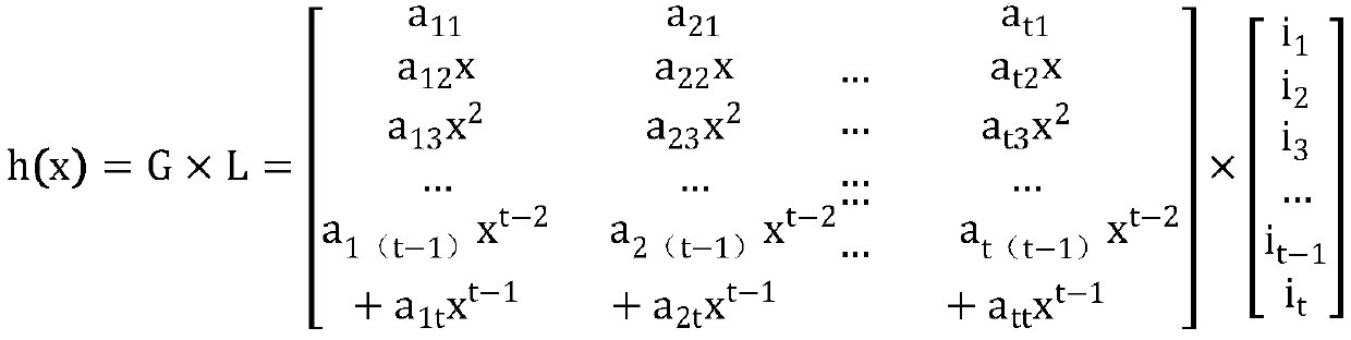
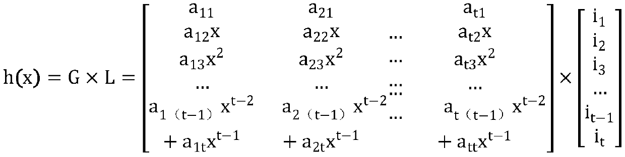
[0043] The controller generates switch path verification identifiers A, B, and C of a service chain according to the polynomial, and configures them on the switch respectively. When the data packet passes through the switch, it will trigger a packet_in message to be sent to the controller, carrying the switch path verification identifier, indicating that the data packet After passing through the switch currently, when the data packet reaches the destination, the controller collects the switch path verification identifier sent by the switch through which the data packet passes. Flow1 results in switches S1, S2, and S4, and sends them to controllers A, B, and C for switch path verification IDs. By comparing the switch path v...


PUM


Abstract

The invention discloses a service path verification method for mimicry configuration in mimicry defense. The method disclosed in the invention comprises the following steps sharing a polynomial algorithm according to the secret of Shanmir via a controller; generating a polynomial for each service path, generating a corresponding switch path verification identifier sequence pair by utilizing the generated polynomial and the unique path identifier of each switch, and then sequentially configuring corresponding sequence values into the switches through a controller. When a data packet passes through a switch, a Packet _ in message is triggered to be sent to a controller, the message carries a switch path verification identifier and indicates that the data packet currently passes through the switch; when the data packet reaches a destination, the controller collects the switch path verification identifier sent by the switch through which the data packet passes. Through grouping and screening the switch path verification identification sequence pairs of different service chains, the SDN can compare the data and analyze whether the corresponding service chains are correctly deployed. Thedefense capability of the network space is improved.

Description

technical field [0001] The invention belongs to the technical field of network communication, and in particular relates to a service path verification method for mimic configuration in mimic defense. Background technique [0002] In the SDN network architecture, this technology of separation of forwarding and control realizes the control of the entire network by means of a centralized controller and simplifies network configuration management. For the underlying network equipment, users can control the network equipment through the open interface of the upper layer, which brings great convenience to the configuration of service deployment. The business deployment of the traditional service chain is based on the physical topology structure, and hardware devices are connected to the transmission path of the business data flow. The network deployment is complex, and the physical network topology structure needs to be changed when the business changes, which is inefficient and p...

Claims


Application Information

Patent Timeline
IPC IPC(8): H04L29/06
CPCH04L63/1441H04L63/08H04L63/205
Inventor 高明焦海罗锦应丽莉周慧颖
Owner ZHEJIANG GONGSHANG UNIVERSITY
Why Eureka
Try Eureka