Supercharge Your Innovation With Domain-Expert AI Agents!

Manufacturing and machining process of cold-rolled channel steel

A processing technology, channel steel technology, applied in the field of steel manufacturing and processing, can solve the problems of material inconsistency, low channel steel production efficiency, long processing time, etc., to achieve the effect of reducing grinding time, improving grinding efficiency, and avoiding secondary processing

Active Publication Date: 2020-06-05
惠民万顺节能新材料有限公司
View PDF5 Cites 4 Cited by
  • Summary
  • Abstract
  • Description
  • Claims
  • Application Information

AI Technical Summary

Problems solved by technology

[0004] (1) When grinding the cold-rolled channel steel by manual grinding, because the inner space of the channel steel is small, it is difficult to manually grind the space inside the channel steel, so that the surface treatment of the channel steel is not thorough, and the channel steel Stains on the outside of the steel need to be manually removed, and the stain removal process is cumbersome, resulting in low production efficiency of channel steel;
[0005] (2) When the existing cold-rolled channel steel manufacturing equipment is manufacturing and processing the cold-rolled channel steel, because the existing grinding equipment usually fixes the cold-rolled channel steel first, and then grinds the inner and outer surfaces sequentially , The processing time is long. During the processing, the grinding equipment is easy to bend the middle part of the longer channel steel, so that the materials removed by grinding the middle part of the channel steel and the two ends are inconsistent, resulting in the need for secondary processing of the channel steel.

Method used


Image

  • Manufacturing and machining process of cold-rolled channel steel
  • Manufacturing and machining process of cold-rolled channel steel
  • Manufacturing and machining process of cold-rolled channel steel

Examples


Embodiment Construction

[0038] In order to make the technical means, creative features, objectives and effects of the present invention easy to understand, the following is combined Figure 1 to Figure 10 , To further explain the present invention.

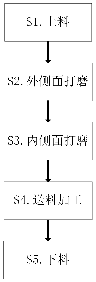
[0039] A manufacturing process of cold rolled channel steel, the specific manufacturing process is as follows:

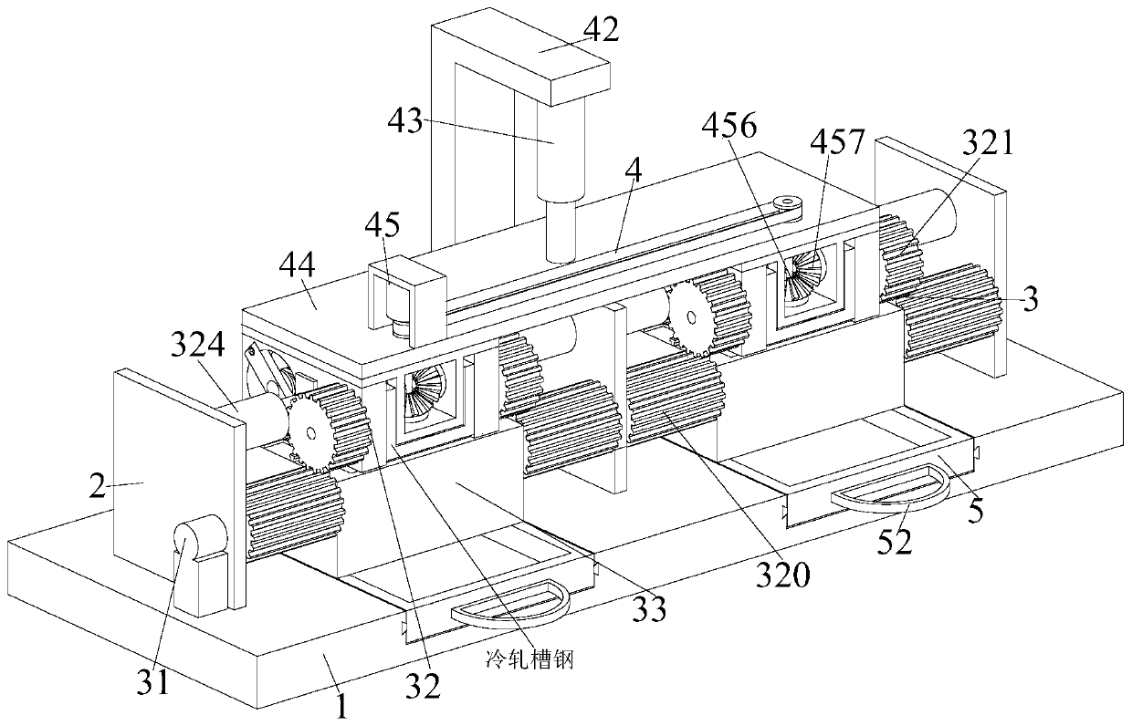
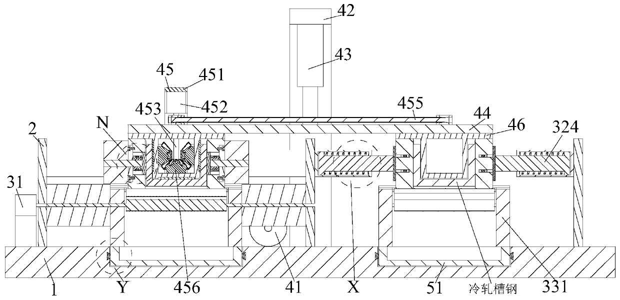
[0040] S1. Feeding: manually place the cold-rolled channel steel on the lower end grinding mechanism 33, so that the side end grinding mechanism 32 is attached to both sides of the cold-rolled channel steel, and the air pump 41 drives the cylinder 43 down, so that the rotating mechanism 45 is attached Fit on the inner surface of cold rolled channel steel;

[0041] S2. Grinding of the outer surface: The rotating motor 31 rotates, thereby driving the side grinding mechanism 32 and the lower grinding mechanism 33 to rotate, so that the long gear 320 drives the sliding gear 321 to rotate, so that the cleaning disk 327 cleans the outer side of the cold-r...


PUM


Abstract

The invention relates to a manufacturing and machining process of cold-rolled channel steel. The manufacturing and machining process comprises a bottom plate, side plates, two sliding grinding devices, lifting grinding devices and two collecting frames, the side plates are evenly welded to the upper end of the bottom plate, the sliding grinding devices are arranged between the side plates, the sliding grinding devices are installed on the bottom plate, the lifting grinding devices are installed on the sliding grinding devices, and the collecting frames are installed on the bottom plate. According to the manufacturing and machining process of the cold-rolled channel steel, the problems that the space inside the channel steel is small during manual grinding, thus it is difficult to grind thespace inside the channel steel manually, the manual decontamination process is tedious, when an existing cold-rolling channel steel manufacturing device machines, the channel steel is usually fixed first after cold-rolling, then the inner and outer surfaces of the channel steel are grinded, the middle of the channel steel is prone to being bended by a grinding device, thus materials removed by grinding the middle and the two ends of the channel steel are inconsistent, so that the channel steel needs to machined again can be solved.

Description

Technical field [0001] The invention relates to the technical field of steel manufacturing and processing, in particular to a cold-rolled channel steel manufacturing and processing technology. Background technique [0002] Channel steel is a long strip of steel with a groove-shaped section. Channel steel is mainly used in building structures, vehicle manufacturing and other industrial structures. Channel steel is often used in conjunction with I-beam. Channel steel is cold-rolled and formed. Burrs are prone to appear at the edges and corners of the steel. After the channel steel is cold-rolled and formed, the channel steel is usually cut by a channel steel cutter or a saw blade, so that the channel steel is convenient for transportation. After the sheet is damaged, it is very easy to have the phenomenon of tearing of the sheared part of the channel steel and more burrs, so it is necessary to de-grind the surface of the channel steel after cold rolling. [0003] The existing cold-r...

Claims


Application Information

Patent Timeline
IPC IPC(8): B24B1/00B24B27/00B24B41/00B24B41/02
CPCB24B1/00B24B27/0076B24B41/00B24B41/02
Inventor 武金峰谢祥松
Owner 惠民万顺节能新材料有限公司
Features
  • R&D
  • Intellectual Property
  • Life Sciences
  • Materials
  • Tech Scout
  • Unparalleled Data Quality
  • Higher Quality Content
  • 60% Fewer Hallucinations
Learn More