Grabbing mechanism or railway wrist arm mounting robot

A grasping mechanism and robot technology, applied in the direction of lifting equipment safety device, manipulator, lifting device, etc., can solve the problem of inability to achieve precise adjustment, and achieve the effects of high installation and movement efficiency, improved installation efficiency, and high convenience.

Pending Publication Date: 2020-06-05
北京圭目智能科技有限公司
View PDF0 Cites 0 Cited by
  • Summary
  • Abstract
  • Description
  • Claims
  • Application Information

AI Technical Summary

Problems solved by technology

However, there is no matching grabbing mechanism in the prior art, and prec

Method used


Image

  • Grabbing mechanism or railway wrist arm mounting robot
  • Grabbing mechanism or railway wrist arm mounting robot
  • Grabbing mechanism or railway wrist arm mounting robot

Examples


Embodiment

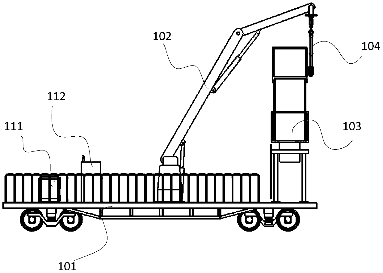
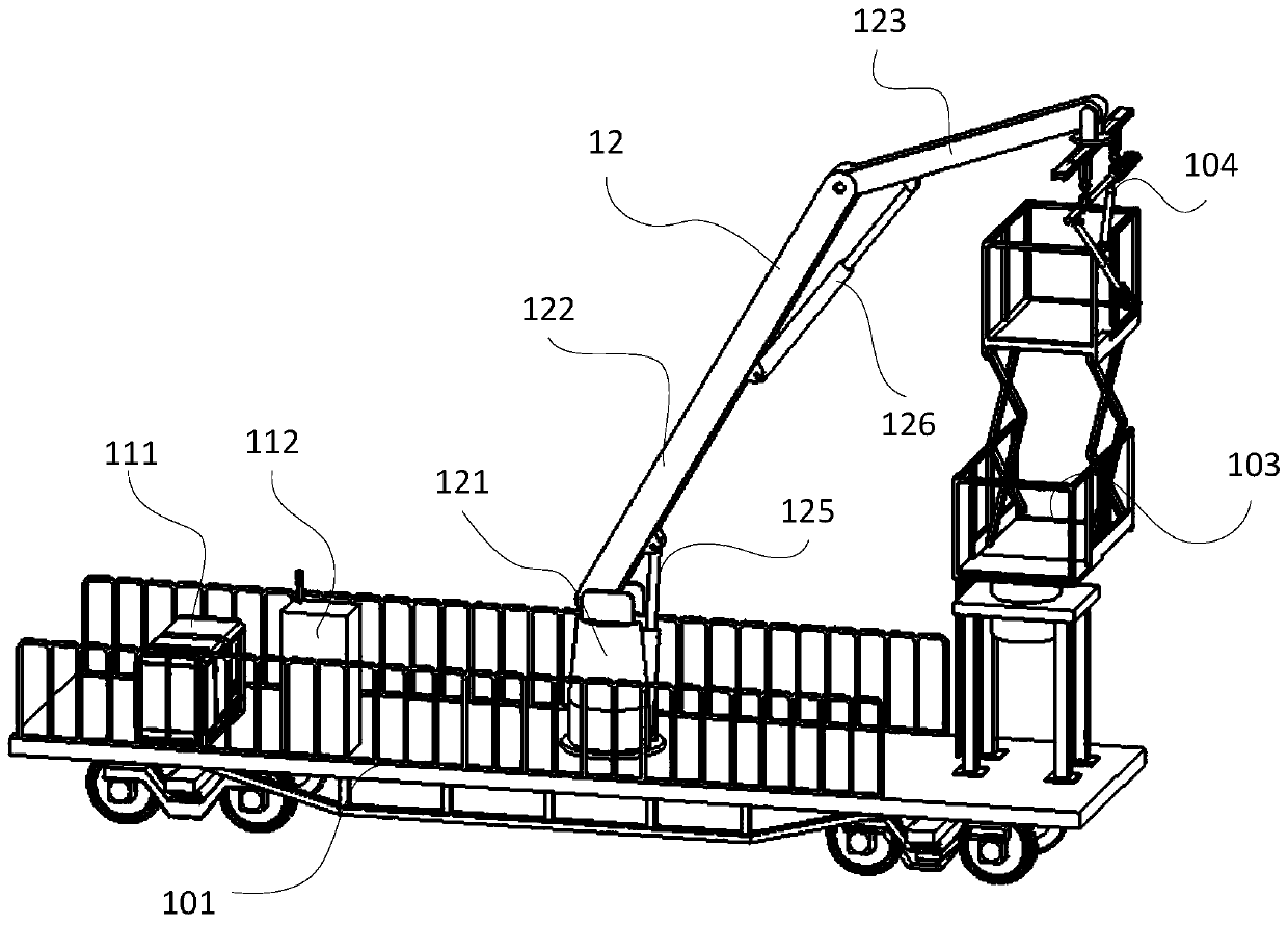
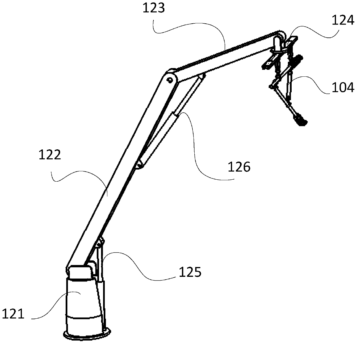
[0035] Such as Figure 1 to Figure 9 As shown, this embodiment provides a railway arm arm installation robot, which travels along the track direction and lifts the arm arm 104 to the installation position of the catenary pillar. It should be noted that the serial numbers such as "first" and "second" in this embodiment are only used to distinguish similar components, and should not be understood as specific limitations on the scope of protection. In addition, directional terms such as "bottom", "top", "surrounding edge", and "center" in this embodiment are described based on the drawings. In addition, the structure of the track vehicle in this embodiment is similar to that of the track inspection vehicle, so its internal structure will not be described in detail here; not only that, the control box in this embodiment is purchased, and it is obtained by wiring conventional controllers and electrical components. , and the control program can be realized by a combination of conve...


PUM


Abstract

The invention discloses a grabbing mechanism for a railway wrist arm mounting robot. The grabbing mechanism comprises a grabbing mechanism mounting seat, a horizontal moving sliding rail fixed at thebottom of the grabbing mechanism mounting seat, a left grabbing mechanism and a right grabbing mechanism, wherein the left grabbing mechanism and the right grabbing mechanism are arranged at the bottom of the horizontal moving sliding rail and used for grabbing a wrist arm; the left grabbing mechanism and the right grabbing mechanism have the same structure; and the right grabbing mechanism comprises a grabbing buckle mounting seat which is fixed at the bottom of the horizontal moving sliding rail and is in a groove shape, an electric cylinder which is fixed in the groove shape of the grabbingbuckle mounting seat and electrically connected with a control box, a cross rod which is connected with the electric cylinder and driven by the electric cylinder to move forwards and backwards, two steel wire ropes with one ends in one-to-one correspondence connection with the two ends of the cross rod, a revering wheel arranged on the grabbing buckle mounting seat and used for steel wire rope reversing, a hoisting plate connected with the other end of any steel wire rope, and a self-locking grabbing buckle arranged on the lower portion of the hoisting plate and used for grabbing the wrist arm.

Description

technical field [0001] The invention relates to the technical field of wrist-arm installation, in particular to a grabbing mechanism for a railway wrist-arm installation robot. Background technique [0002] The wrist arm is installed on the pillar to support the contact suspension and play the role of transferring load; according to the structure of the wrist arm, it can be divided into a horizontal wrist arm with a pull rod, a flat wrist arm with a diagonal brace and a pull rod (or pressure tube) ) slanted wrist arms, etc.; at present, the installation of the wrist arms in the prior art is mainly manual, and each group of wrist arms needs to be equipped with at least 5 to 7 operators, and its work efficiency is too low; and, the wrist arms The weight is about 200Kg, and it is laborious to lift; in addition, there is also a lifting trolley to install the wrist arm, and the fixing steps before installation are relatively cumbersome. Rollover accident; not only that, it is mo...

Claims


Application Information

Patent Timeline
IPC IPC(8): B25J5/02B25J11/00B25J15/00B60M1/28B60M1/20B66F11/04B66F13/00B66F17/00F15B21/08F15B21/0423F15B20/00
CPCB25J5/02B25J11/00B25J15/00B60M1/20B60M1/28B66F11/046B66F13/00B66F17/006F15B20/007F15B21/0423F15B21/087
Inventor 凌正刚周辉肖唐杰王云飞桂仲成
Owner 北京圭目智能科技有限公司
Why Eureka
Try Eureka