Power ventilating system used for elevator

A ventilation system and electric power technology, applied in the field of electric power, can solve the problems of reducing the use cost of the traction machine, poor ventilation of hospital elevators, etc., and achieve the effect of saving electric energy, reducing the use of power, and saving the use of electric energy

Pending Publication Date: 2020-06-05
谭永强
View PDF0 Cites 4 Cited by
  • Summary
  • Abstract
  • Description
  • Claims
  • Application Information

AI Technical Summary

Problems solved by technology

[0007] The purpose of the present invention is to provide an electric ventilation system for elevators. This system can timely discharge the air inside the elevator shaft and the fresh air in the external environment through the blowing of the axial flow fan and the control of the gravity switch. The exchange of dust and filtration through the car ventilation device blows into the car to provide fresh air inside the car and solve the problem of poor ventilation in existing hospital elevators; the axial flow fan can be used in the car under the control of the gravity switch. When the car is going up, the air on the upper part of the car is sucked out of the external environment, and the outside air is blown into the space below the car. Reduce the load of the traction machine, reduce the use cost of the traction machine; at the same time, it also has the cleaning function

Method used


Image

  • Power ventilating system used for elevator
  • Power ventilating system used for elevator
  • Power ventilating system used for elevator

Examples


Embodiment Construction

[0038] Embodiments of the present invention are described in detail below, examples of which are shown in the drawings, wherein the same or similar reference numerals designate the same or similar elements or elements having the same or similar functions throughout. The embodiments described below by referring to the figures are exemplary and are intended to explain the present invention and should not be construed as limiting the present invention.

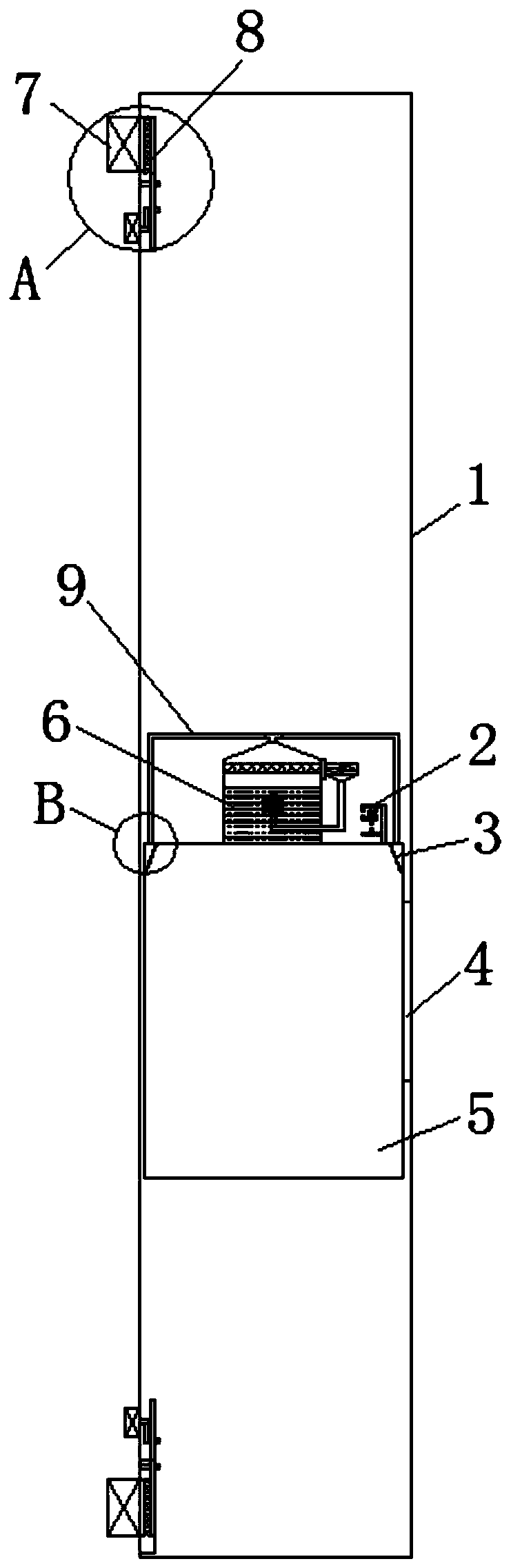
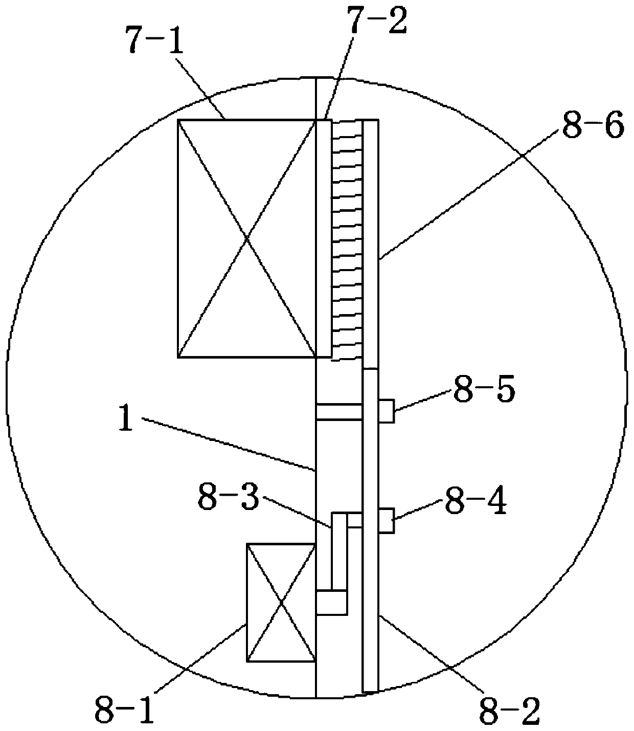
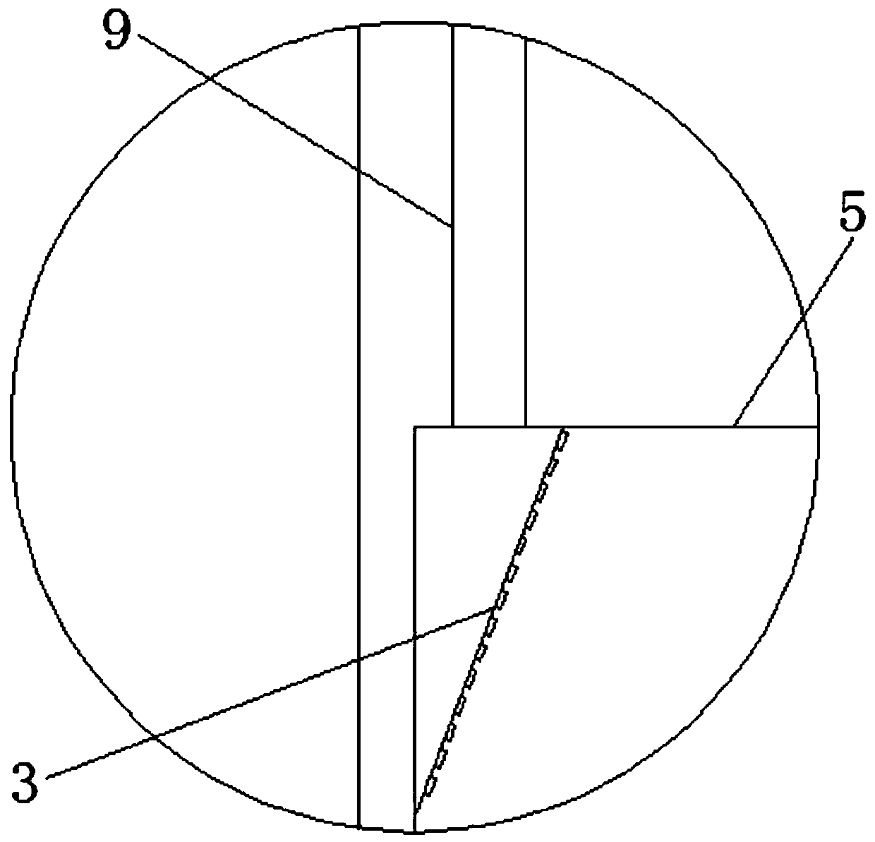
[0039] Such as Figure 1-10 As shown, an electric ventilation system for an elevator includes an elevator shaft 1, a gravity switch 2, an air outlet plate 3, a car door 4, a car 5, a car ventilation device 6, a shaft ventilation device 7, and an auxiliary cleaning device 8. The air supply pipe 9 and the touch switch 10, the top and bottom of the elevator shaft 1 are provided with a shaft ventilation device 7 outside, and the inside is provided with an auxiliary cleaning device 8, and the elevator shaft 1 is provided with a car 5,...


PUM


Abstract

The invention discloses a power ventilating system used for an elevator. The power ventilating system comprises an elevator shaft, a gravity switch, an air outlet plate, car doors, a car, a car ventilating device, a shaft ventilating device, an auxiliary clearing device, an air inlet tube and touch switches, wherein the shaft ventilating device is arranged outside the top and the bottom of the elevator shaft, and the auxiliary clearing device is arranged inside the elevator shaft; the car is arranged in the elevator shaft; one side of the car is provided with the car doors; the opposite sidesof the car doors are provided with the touch switches; the touch switches are electrically connected to the car ventilating device; the gravity switch and the car ventilating device are arranged outside the top of the car, and the air outlet plate is arranged inside the top of the car; the car ventilating device communicates with the air outlet plate through the air feeding tube; and the gravity switch is electrically connected to the shaft ventilating device. The power ventilating system has the advantages of being energy-saving and environmentally friendly, reducing use energy consumption ofelectric energy, being capable of timely replacing air inside the car, and being further provided with a clearing function.

Description

technical field [0001] The invention relates to the field of electric power, and more belongs to the technical field of elevators, in particular to an electric power ventilation system for elevators. Background technique [0002] Elevator is a kind of vertical elevator powered by electric motor, which is used for the transportation of people or goods in multi-storey buildings. With the rapid development of social economy and the continuous improvement of living standards, elevators have become an indispensable part of daily life. [0003] At present, the elevator industry is getting better and better and more exquisite, but with the good development of workmanship, the inside of the elevator is too airtight and the ventilation is poor, which leads to adverse reactions when taking the elevator, and the feeling of taking the elevator is greatly reduced. Especially for elevators used in hospitals, the environment has a strong smell of medicine, and passengers are likely to caus...

Claims


Application Information

Patent Timeline
Patent Type & Authority Applications(China)
IPC IPC(8): B66B11/02B08B1/00B08B1/04F24F7/007
CPCB08B1/002B08B1/04B66B11/024F24F7/007
Inventor 谭永强
Owner 谭永强
Why Eureka
Try Eureka