Foldable fire-fighting pipeline roof mounting lifting device

A technology of fire-fighting pipelines and lifting devices, which is applied in the direction of lifting devices, lifting frames, etc., can solve the problems of low installation efficiency and high labor intensity, and achieve the effects of improving installation efficiency, reducing labor intensity, and reducing labor intensity

Active Publication Date: 2020-06-05
浙江振大实业建设有限公司
View PDF9 Cites 11 Cited by
  • Summary
  • Abstract
  • Description
  • Claims
  • Application Information

AI Technical Summary

Problems solved by technology

[0005] In order to overcome the disadvantages that workers need to carry and support the fire-fighting pipeline by hand during the installation of the fire-fighting pipeline, and the labor intensity is high, and the installation efficiency is low. The labor intensity of the workers is small, the installation efficiency of the fire pipe is improved, and the lifting device is installed on the roof of the foldable fire pipe without causing accidents

Method used


Image

  • Foldable fire-fighting pipeline roof mounting lifting device
  • Foldable fire-fighting pipeline roof mounting lifting device
  • Foldable fire-fighting pipeline roof mounting lifting device

Examples


Embodiment 1

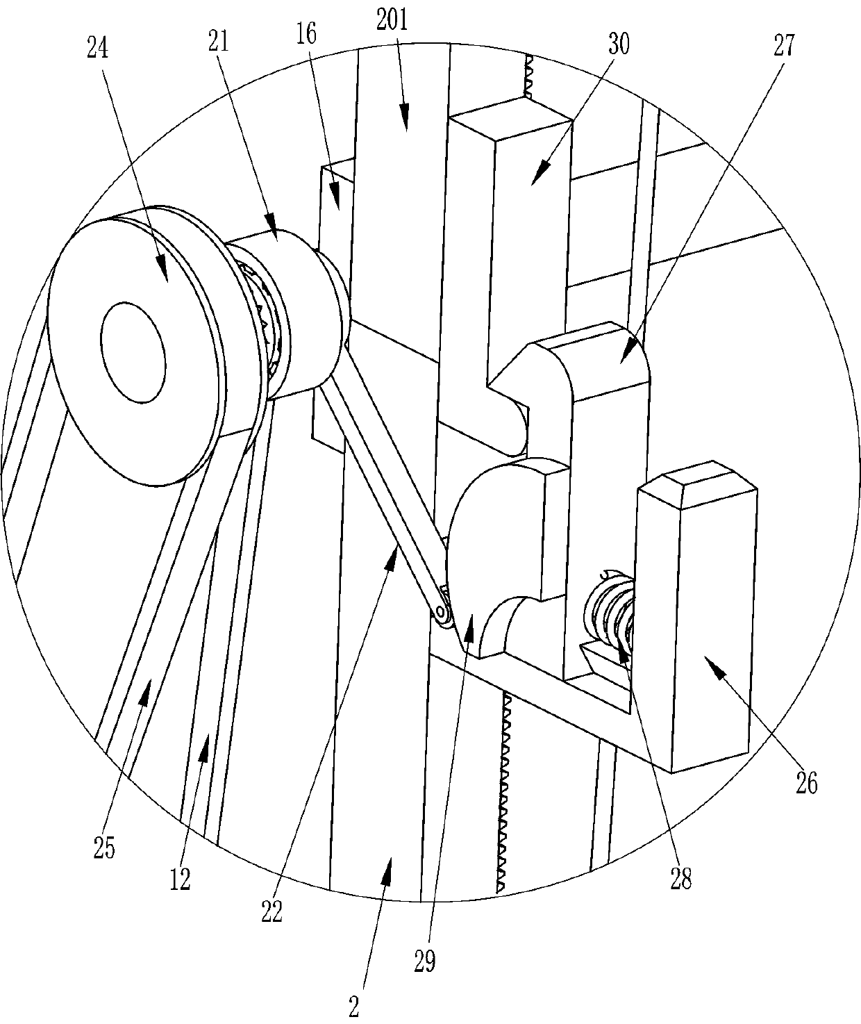
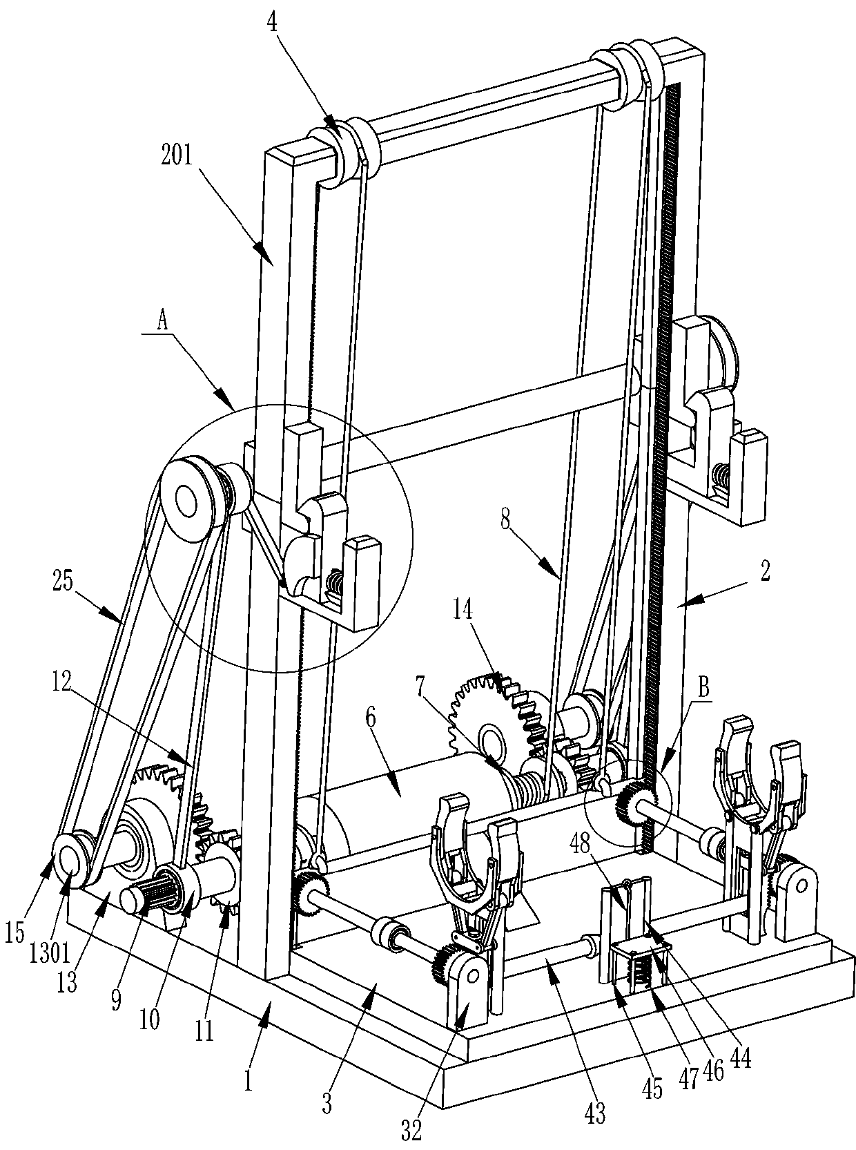
[0023] see Figure 1-Figure 4 , a kind of foldable fire-fighting pipe roof installation lifting device, including base 1, lifting frame 2, swing frame 201, lifting mechanism, biaxial motor 6 and turning mechanism, the left and right sides of the middle of the top of base 1 are fixedly connected with Lifting frame 2, a swinging frame 201 is hinged between the tops of the lifting frame 2 on the left and right sides, a lifting mechanism is provided between the swinging frame 201 and the lifting frame 2, and a flipping mechanism is provided between the lifting frame 2 and the base 1 and the rear side of the swinging frame 201. mechanism, the biaxial motor 6 is installed on the top rear side of the base 1, and the biaxial motor 6 is connected with the turning mechanism and the lifting mechanism.

[0024] The lifting mechanism includes an L-shaped slide plate 3, a scroll wheel 4, a suspension ring 5, a reel 7, a wire rope 8, a support rod 36 and a U-shaped block 37, and the left and...

Embodiment 2

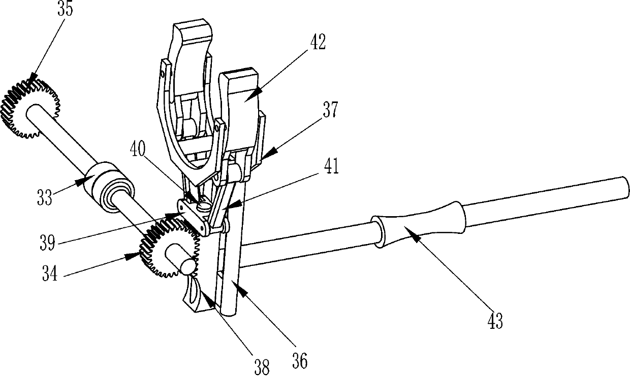
[0030] see figure 1 , figure 2 with Figure 5 Compared with Embodiment 1, the main difference of this embodiment is that this embodiment also includes a first rack 31, a second support plate 32, a one-way shaft 33, a third gear 34, a fourth gear 35, a second Rack 38, connecting block 39, the first slide bar 40, the second push rod 41, clip block 42 and pull bar 43, the left and right sides of the front side of the inner bottom of the L-shaped slide plate 3 are all affixed with the second support plate 32, the second The support plate 32 is located at the outside of the support rod 36, the top of the second support plate 32 is rotatably connected with a one-way shaft 33, the rear end of the one-way shaft 33 is fixedly connected with a fourth gear 35, and the front portion of the one-way shaft 33 is fixedly connected with a third The gear 34, the left and right sides of the inner bottom of the L-shaped skateboard 3 are fixedly connected with the first slide bar 40, the first ...

Embodiment 3

[0033] see figure 1 , the main difference between this embodiment and embodiment 1 and embodiment 2 is that this embodiment also includes a third support plate 44, a second slide bar 45, a pedal 46, a second elastic member 47 and a pull wire 48, L Four second slide bars 45 are fixedly connected to the middle part of the inner bottom of the type skateboard 3, and pedals 46 are slidingly provided between the four second slide bars 45. The second elastic member 47 is connected with a pull wire 48 at the middle part of the rear side of the pedal 46, and the third support plate 44 is fixedly connected with the front middle part of the inner bottom of the L-shaped slide plate 3, and the third support plate 44 is located between the pull bar 43 and the second slide bar 45. The tail end of the pull wire 48 is fixedly connected to the middle of the pull rod 43 around the top of the third support plate 44 .

[0034] When the fire-fighting pipeline is placed between the u-shaped blocks ...


PUM


Abstract

The invention relates to a lifting device, in particular to a foldable fire-fighting pipeline roof mounting lifting device. The foldable fire-fighting pipeline roof mounting lifting device solves thetechnical problem that a fire-fighting pipeline can be automatically lifted, the labor intensity of workers is reduced, the mounting efficiency of the fire-fighting pipeline is improved, and accidentsare avoided. The foldable fire-fighting pipeline roof mounting lifting device comprises a base, lifting frames are symmetrically and fixedly connected to one side of the top of the base, a swing frame is hinged between the ends, away from the base, of the lifting frames on the two sides, and a double-shaft motor is installed on the side, close to the lifting frames, of the base. The lifting frames can be folded and stretched through a turnover mechanism, a lifting mechanism lifts the fire-fighting pipeline, the labor intensity of the workers is reduced, the installation efficiency of the fire-fighting pipeline is improved, and the accidents cannot be caused.

Description

technical field [0001] The invention relates to a lifting device, in particular to a foldable lifting device installed on the roof of a fire-fighting pipeline. Background technique [0002] Fire-fighting pipes are used to connect fire-fighting equipment and equipment, and transport fire-fighting water, gas or other medium pipe materials. Fire-fighting pipes are usually made of iron. In some large buildings, fire-fighting pipes need to be installed to prevent fires. Timely extinguishing the fire caused huge losses. Where necessary, fire-fighting pipes need to be installed to avoid dangerous accidents caused by fire in daily life. [0003] At present, when workers install fire-fighting pipelines, most of them carry and support the fire-fighting pipelines by hand, and some of the fire-fighting pipelines must be fixed on the top of the building. Workers need to carry the fire-fighting pipelines to the top of the building, so that workers The labor intensity is very high, which...

Claims


Application Information

Patent Timeline
Patent Type & Authority Applications(China)
IPC IPC(8): B66F7/02B66F7/28
CPCB66F7/02B66F7/28
Inventor 不公告发明人
Owner 浙江振大实业建设有限公司
Why Eureka
Try Eureka