
Concealed drainage sliding door

A sliding door, hidden technology, applied in the direction of windows/doors, door/window fittings, condensate discharge, etc., can solve the problems of indoor water ingress and water falling, and achieve the effect of reducing the possibility of stepping on the air

Active Publication Date: 2021-05-11
重庆市驰茂装饰工程有限公司
View PDF7 Cites 0 Cited by
  • Summary
  • Abstract
  • Description
  • Claims
  • Application Information

AI Technical Summary

Problems solved by technology

[0004] The above-mentioned existing technical solutions have the following defects: when drying clothes or in rainy days, water will fall on the ground of the balcony, which may cause indoor water ingress

Method used


Image

  • Concealed drainage sliding door
  • Concealed drainage sliding door
  • Concealed drainage sliding door

Examples


Embodiment 1

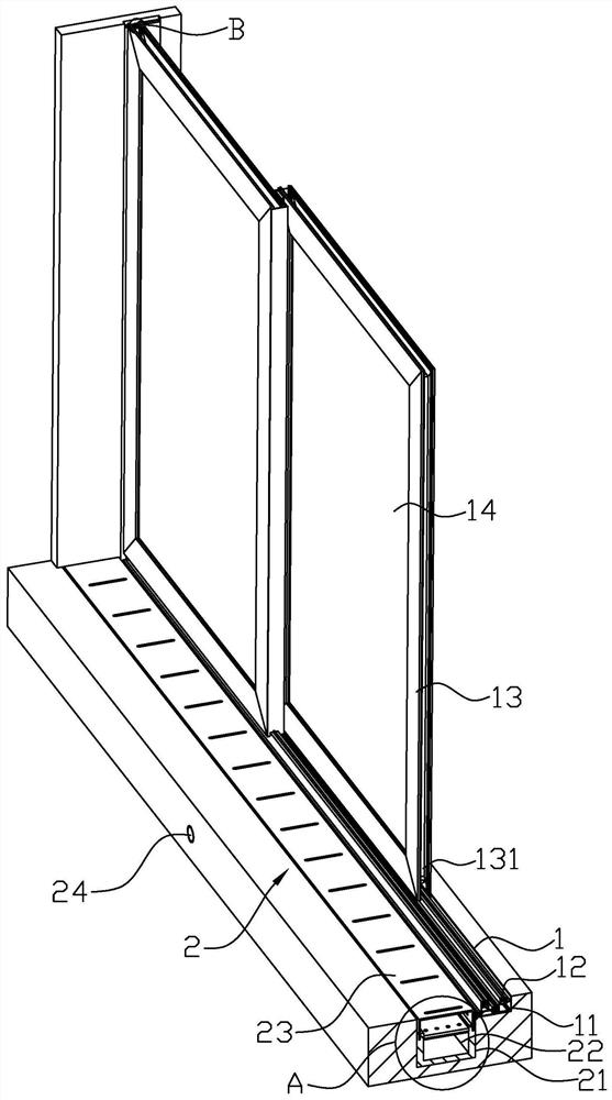
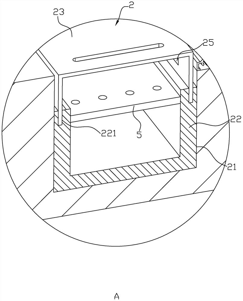
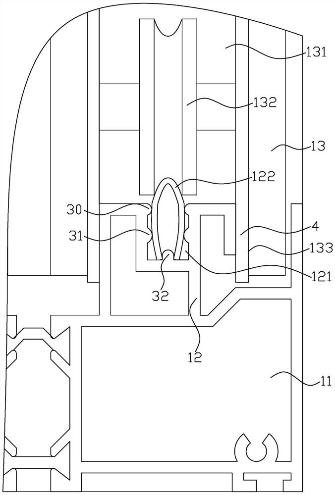
[0039] Embodiment 1: A hidden drainage sliding door, such as figure 1 and image 3 As shown, it includes a first installation groove 1, a frame 11 installed in the first installation groove 1, two first guide rails 12 respectively installed on both sides of the bottom of the frame 11, and two first guide rails 12 slidingly connected to the two first guide rails 12. A door frame 13 and two glass blocks 14 installed on the two door frames 13; the two sides of the door frame 13 near one end of the frame 11 are respectively fixed with a second rubber layer 15 (see Figure 4 ), the bottom of each door frame 13 is provided with a first strip groove 131, the two ends of the first strip groove 131 are respectively equipped with rollers 132, the top of the first guide rail 12 is provided with a second strip groove 121, the second A second guide rail 122 is installed in the shaped groove 121, each roller 132 is rollingly connected to the second guide rail 122, and a drainage device 2 i...

Embodiment 2

[0045] Embodiment 2: A hidden drainage sliding door, such as Figure 5 and Figure 6 As shown, the main difference from Embodiment 1 is that a fixing device 6 for fixing the filter plate 5 is installed in the first drain pipe 22, and the fixing device 6 includes a support ring 61 horizontally fixed in the first drain pipe 22 and respectively Two groups of plug-in mechanisms 7 installed in two first slots 221; A plurality of through-holes 71 and one-to-one correspondingly slidingly connected to the through-holes 71 along the width direction of the first drain pipe 22; the corresponding plug-in blocks 72 are respectively provided with second slots on both sides of the filter plate 5 73, the plug blocks 72 are plugged into the second slot 73 one by one; one side of each plug block 72 is equipped with a reset assembly 74 for resetting the plug block 72, and the reset assembly 74 includes a The sliding sleeve 741 on the side, the guide rod 742 fixed on the side of the first slot ...


PUM


Abstract

The invention relates to a hidden drainage sliding door, which comprises a first installation groove, a frame, two first guide rails, two door frames slidingly connected to the two first guide rails, and two glass blocks installed on the two door frames , the bottom of each door frame is provided with a first bar-shaped groove, rollers are respectively installed at both ends of the first bar-shaped groove, the top of the first guide rail is provided with a second bar-shaped groove, and a second bar-shaped groove is installed in the second bar-shaped groove Each roller is rollingly connected to the second guide rail. A drainage device is installed on the side of the first installation groove close to the balcony. The drainage device includes a second installation groove opened on the side of the first installation groove near the balcony and fixed on the second The first drain pipe in the installation groove, the water grate installed on the top of the first drain pipe, and the second drain pipe connected to one side of the first drain pipe; hole; the second drain pipe communicates with the downpipe. The present invention can reduce the possibility of indoor water ingress by arranging the drainage device.

Description

technical field [0001] The invention relates to the technical field of sliding doors, in particular to a hidden drainage sliding door. Background technique [0002] A sliding door is a commonly used door in the home, which refers to a door that can be pushed and pulled. With the development of technology and the diversification of decoration methods, sliding doors have changed from traditional plate surfaces to glass, fabric, rattan, aluminum alloy profiles, from sliding doors, folding doors to partition doors, and the functions and scope of use of sliding doors are constantly changing. expand. [0003] The prior art can refer to the Chinese utility model patent whose authorized notification number is CN203188823U, which discloses a sliding door, including a sliding door body, and a walkway frame for the sliding of the sand door is provided around the sliding door body; the walkway frame and The sliding door body is integrally formed. The sliding door body is double-openi...

Claims


Application Information

Patent Timeline
Patent Type & Authority Patents(China)
IPC IPC(8): E06B3/46E06B7/14E05D15/06E05F5/06B01D29/05B01D29/96
CPCB01D29/05B01D29/96E05D15/0686E05F5/06E05Y2900/132E06B3/4636E06B7/14
Inventor 李兵皮志高
Owner 重庆市驰茂装饰工程有限公司
Learn More