Boost jet nozzle for blockage removal of air pre-heater of heat-engine plant

A technology of air preheater and thermal power plant, which is applied to injection devices, removal of solid residues, liquid injection devices, etc., can solve the problems of insufficient heat exchange efficiency of air preheaters, threatening the safe operation of boilers, and difficult cleaning and construction, etc. Improve the effect of clearing blockage, improve blocking efficiency, and enhance efficiency

Pending Publication Date: 2020-06-05
MANZHOULI DALAIHU THERMAL POWER CO LTD
View PDF0 Cites 0 Cited by
  • Summary
  • Abstract
  • Description
  • Claims
  • Application Information

AI Technical Summary

Problems solved by technology

[0002] As we all know, when the power plant boiler is in operation, two types of ash deposits and salt deposits, loose and cohesive, often appear inside the tube bundle of the surface tube air preheater. The heat transfer efficiency of the air preheater is insufficient, and the safe operation of the boiler will be threatened in the case of serious blockage. The internal blockage of the conventional air preheater tube bundle is dredged by mechanical impact, compressed air, and water gun, while mechanical and compressed air dredging, It is effective for the loosening and dust accumulation in the air preheater, but it does not have the ability to clean the hardening and salt formation. The high-pressure water gun has a certain cleaning effect on the hardening and salt formation, but the efficiency of conventional high-pressure washing is low. At the same time, the gun head There is a reverse force, and the cleaning construction is more difficult

Method used


Image

  • Boost jet nozzle for blockage removal of air pre-heater of heat-engine plant

Examples


Embodiment Construction

[0010] The specific implementation manners of the present invention will be further described in detail below in conjunction with the accompanying drawings and embodiments. The following examples are used to illustrate the present invention, but are not intended to limit the scope of the present invention.

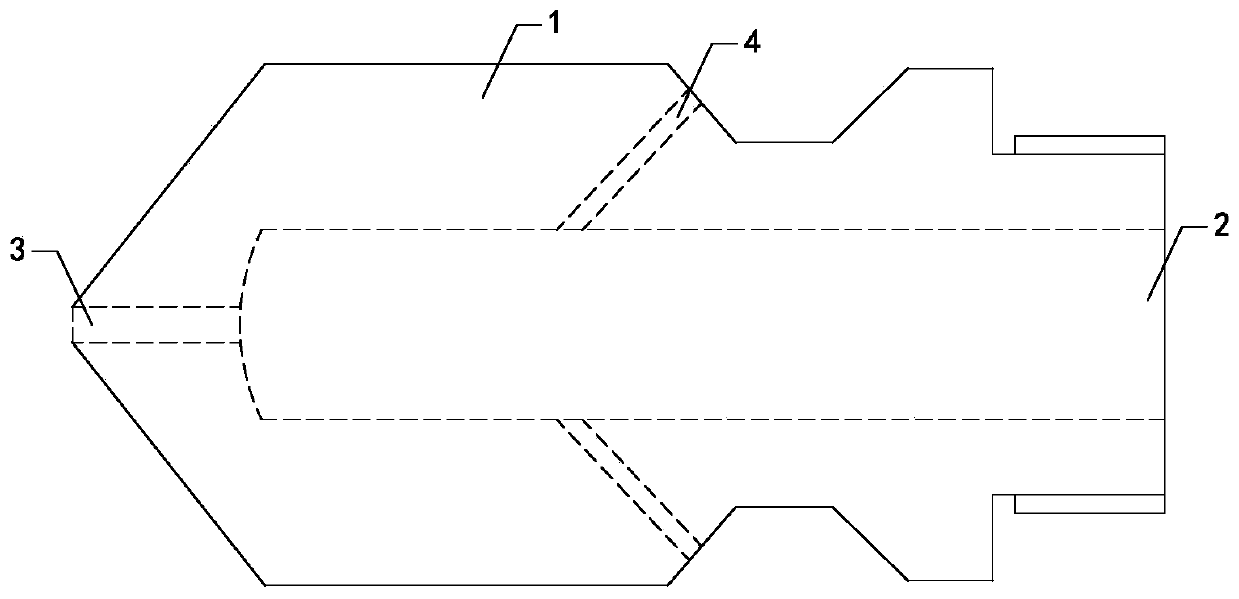
[0011] Such as figure 1 As shown, a thermal power plant air preheater blockage cleaning booster jet nozzle of the present invention includes a nozzle body 1, a groove 2 is provided at the right end of the nozzle body 1, a jet impact nozzle 3 is provided at the left end of the nozzle body 1, and a jet impact nozzle 3 The right end is connected with the left end of the groove 2, and the right side of the side wall of the nozzle body 1 is connected with three groups of booster nozzles 4, and the three groups of three groups of booster nozzles 4 are all connected with the side wall of the groove 2, and the three groups of booster nozzles 4 are connected with the nozzle body. ...


PUM


Abstract

The invention relates to the technical field of boiler cleaning equipment, in particular to a boost jet nozzle for blockage removal of an air pre-heater of a heat-engine plant. The boost jet nozzle can improve the cleaning effect, improve the flushing efficiency, reduce the cleaning construction difficulty caused by counter-acting force, and reduce the cleaning hazards. The boost jet nozzle comprises a nozzle body. A groove is formed in the right end of the nozzle body. A jet impingement nozzle hole is formed in the left end of the nozzle body. The right end of the jet impingement nozzle holecommunicates with the left end of the groove. The right side of the side wall of the nozzle body communicates with and is provided with three groups of boost nozzle holes. The three groups of boost nozzle holes all communicate with the side wall of the groove. The angle of 60 degrees is formed between each boost nozzle hole and the axis of the nozzle body.

Description

technical field [0001] The invention relates to the technical field of boiler cleaning equipment, in particular to a plugging and cleaning booster jet nozzle of an air preheater in a thermal power plant. Background technique [0002] As we all know, when the power plant boiler is in operation, two types of soot and salt deposits, loose and cohesive, often appear inside the tube bundle of the surface tube air preheater. The heat exchange efficiency of the air preheater is insufficient, and the safe operation of the boiler will be threatened in the case of serious blockage. The internal blockage of the conventional air preheater tube bundle is dredged by mechanical impact dredging, compressed air dredging, water gun dredging, etc., while mechanical and compressed air dredging, It is effective for the loosening and dust accumulation in the air preheater, but it does not have the ability to clean the compaction and salt formation. The high-pressure water gun has a certain flushi...

Claims


Application Information

Patent Timeline
Patent Type & Authority Applications(China)
IPC IPC(8): F23L15/04F23J3/02B05B7/02
CPCB05B7/02F23J3/02F23L15/04Y02E20/34
Inventor 于龙韩双江苏德杨雪山刘兴伟高连达张升田
Owner MANZHOULI DALAIHU THERMAL POWER CO LTD
Why Eureka
Try Eureka