Bypass system and method for cascaded multilevel converters
A technology of cascading multi-level and bypass systems, which is applied in the direction of converting irreversible DC power input into AC power output, and can solve problems such as system cost increase
- Summary
- Abstract
- Description
- Claims
- Application Information
AI Technical Summary
Problems solved by technology
Method used
Image
Examples
Embodiment 1
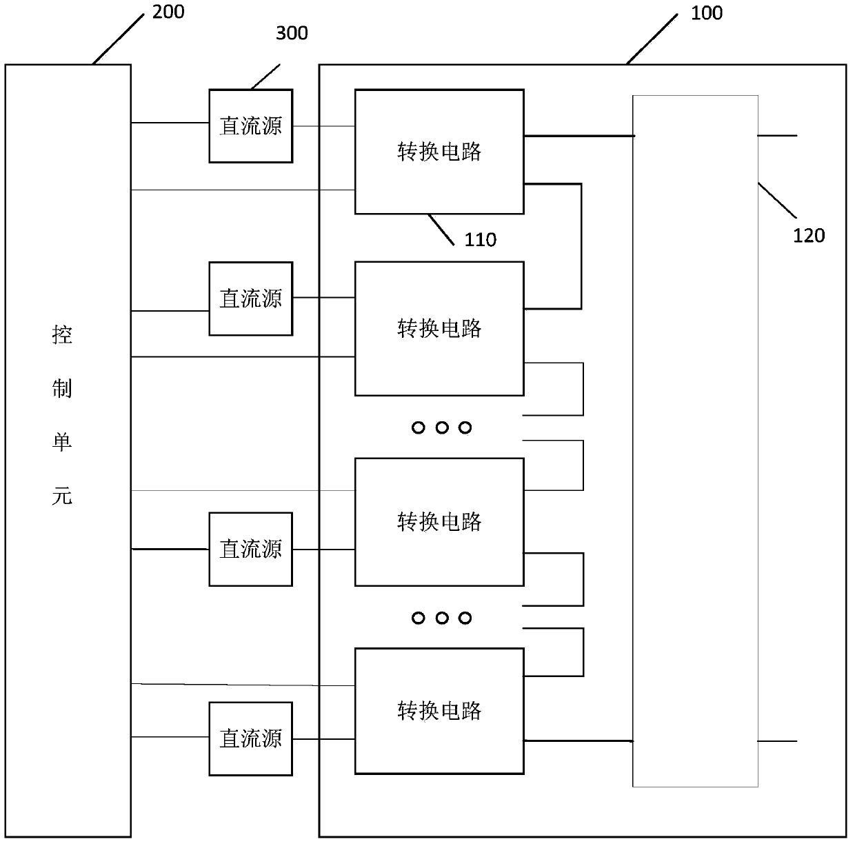
[0041] image 3 It is a schematic structural diagram of the bypass system of the cascaded multilevel converter provided by Embodiment 1 of the present invention.
[0042] like image 3 As shown, a cascaded multilevel converter bypass system provided by Embodiment 1 of the present invention includes a cascaded multilevel converter 100 and a control unit 200;
[0043] Wherein, the cascaded multilevel converter 100 includes at least two cascaded conversion circuits 110, among the at least two conversion circuits 110, the first output terminals and the second output terminals of adjacent conversion circuits 110 are electrically connected in sequence, Each conversion circuit 110 includes a plurality of switch tubes.
[0044] In addition, the conversion circuit 200 is provided in a one-to-one correspondence with the external DC source 300 and electrically connected, and the DC source 300 is used to provide DC power to the corresponding conversion circuit 110 .
[0045]The control...
Embodiment 2
[0048] Figure 4 It is a schematic structural diagram of the conversion circuit in the bypass system of the cascaded multilevel converter provided by Embodiment 2 of the present invention. like Figure 4 As shown, the above at least two conversion circuits 110 each include: a first capacitor 1121 , a first switch tube 1122 , a second switch tube 1123 , a third switch tube 1124 and a fourth switch tube 1125 .
[0049] Wherein, the first end of the first switch tube 1122 is electrically connected to the first end of the second switch tube 1123, the first end of the first capacitor 1121 and the positive pole of the DC source 300 respectively;
[0050] The second end of the first switch tube 1122 is electrically connected to the first end of the third switch tube 1124 and the first output end of the conversion circuit 110 respectively;
[0051] The second end of the second switch tube 1123 is electrically connected to the first end of the fourth switch tube 1125 and the second o...
Embodiment 3
[0063] Different from the first embodiment above, in the bypass system of the cascaded multilevel converter provided by the third embodiment of the present invention, the control unit therein may include a plurality of control sub-modules corresponding to the conversion circuits one-to-one. Image 6 A schematic structural diagram of a bypass system of a cascaded multilevel converter provided in Embodiment 3 of the present invention. like Image 6 As shown, the control unit 200 may include a processor 220 and at least two control sub-modules 210, each control sub-module 210 corresponds to the conversion circuit 110 one by one, and is electrically connected to the corresponding conversion circuit 110 and the DC source 300 respectively, The control sub-module 210 is used to collect the status information of the corresponding conversion circuit 110 and the DC source 300 and send it to the processor 220. The processor 220 confirms the working status of the corresponding conversion ...
PUM
 Abstract
Description
Claims
Application Information
 - R&D
- Intellectual Property
- Life Sciences
- Materials
- Tech Scout
- Unparalleled Data Quality
- Higher Quality Content
- 60% Fewer Hallucinations
Browse by: Latest US Patents, China's latest patents, Technical Efficacy Thesaurus, Application Domain, Technology Topic, Popular Technical Reports.
© 2025 PatSnap. All rights reserved.Legal|Privacy policy|Modern Slavery Act Transparency Statement|Sitemap|About US| Contact US: help@patsnap.com


