
Control method of multi-split air-conditioning system

A multi-connected air conditioner and control method technology, which is applied to air conditioning systems, noise suppression, heating and ventilation control systems, etc., can solve the problems that the multi-connected air conditioner system cannot take into account the cooling capacity and the reduction of heating capacity

Pending Publication Date: 2020-06-05
QINGDAO HAIER AIR CONDITIONER GENERAL CORP LTD +2
View PDF3 Cites 1 Cited by
  • Summary
  • Abstract
  • Description
  • Claims
  • Application Information

AI Technical Summary

Problems solved by technology

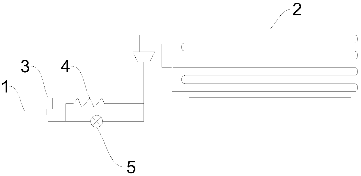
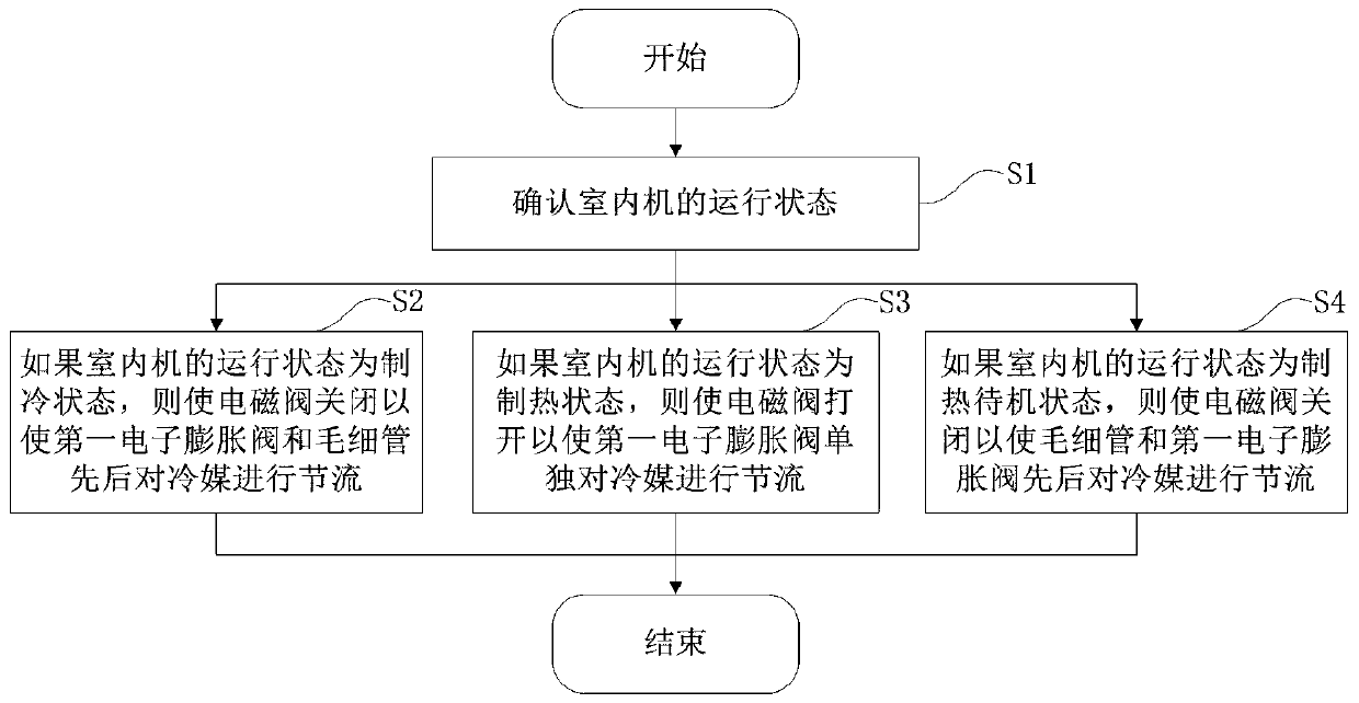
[0005] In order to solve the above-mentioned problems in the prior art, that is, in order to solve the problem that the existing multi-connected air-conditioning system cannot take into account the refrigeration capacity, the heating capacity and the problem of reducing the sound of the refrigerant, the present invention provides a control method for the multi-connected air-conditioning system. The air conditioning system includes an outdoor unit, multiple connecting pipes and multiple indoor units. The connecting pipes correspond to the indoor units one by one. Each indoor unit is connected to the outdoor unit through a connecting pipe. There are a throttling element, an on-off valve and a first electronic expansion valve, the throttling element and the on-off valve are arranged in parallel, and the throttling element and the on-off valve are arranged on the downstream side of the first electronic expansion valve along the refrigerant flow direction when the indoor unit is cold, and the control The method includes: determining the operating state of the indoor unit; selectively opening or closing the on-off valve according to the operating state of the indoor unit, so that the first electronic expansion valve can throttle the refrigerant independently, or make the throttling element and the first electronic expansion valve The valve throttles the refrigerant successively in different order

Method used


Image

  • Control method of multi-split air-conditioning system
  • Control method of multi-split air-conditioning system

Examples


Embodiment Construction

[0015] Preferred embodiments of the present invention are described below with reference to the accompanying drawings. Those skilled in the art should understand that these embodiments are only used to explain the technical principles of the present invention, and are not intended to limit the protection scope of the present invention.

[0016] It should be noted that, in the description of the present invention, terms such as "upper", "lower" and other indicated directions or positional relationships are based on the directions or positional relationships shown in the accompanying drawings, which are only for convenience of description, rather than Nothing to indicate or imply that a device or element must have a particular orientation, be constructed, and operate in a particular orientation should therefore be construed as limiting the invention. In addition, the terms "first" and "second" are used for descriptive purposes only, and should not be understood as indicating or ...


PUM


Abstract

The invention belongs to the technical field of multi-split air-conditioning systems, aims to solve the problem that an existing multi-split air-conditioning system cannot give consideration to refrigeration capacity, heating capacity and refrigerant sound reduction at the same time, and provides a control method of a multi-split air-conditioning system. The system comprises an outdoor unit, a plurality of connecting pipes and a plurality of indoor units. Each connecting pipe is provided with a throttling element, a switch valve and a first electronic expansion valve, wherein the throttling element and the switch valve are arranged in parallel, and the throttling element and the switch valve are arranged on the downstream side of the first electronic expansion valve along the flowing direction of a refrigerant during indoor unit refrigeration. The control method comprises the steps that the running state of the indoor units is determined; and according to the running state of the indoor units, the switch valves are selectively opened or closed so that the first electronic expansion valves can separately throttle the refrigerant, or the throttling elements and the first electronic expansion valves can sequentially throttle the refrigerant in different sequences. The refrigeration capacity, the heating capacity and refrigerant sound reduction can be considered at the same time, and user experience is improved.

Description

technical field [0001] The invention belongs to the technical field of multi-connected air conditioners, and specifically provides a control method for a multi-connected air conditioner system. Background technique [0002] The multi-connected air-conditioning system is currently a commonly used device that can cool / heat indoors, and it is widely used in office buildings, shopping centers, etc. [0003] When the indoor unit is cooling, heating and heating standby, when the refrigerant passes through the electronic expansion valve, it will produce sound due to the throttling effect. This sound will cause trouble to users, especially those who are very sensitive to sound. In the prior art, capillary tubes are usually installed before or after the valve of the electronic expansion valve (both relative to the refrigerant flow direction of the indoor unit during cooling). Refrigeration will lead to vaporization of the refrigerant, increase the dryness of the refrigerant, and cau...

Claims


Application Information

Patent Timeline
IPC IPC(8): F24F1/0003F24F11/30F24F11/64F24F11/84F24F11/88F24F13/24
CPCF24F1/0003F24F11/30F24F11/64F24F11/84F24F11/88F24F13/24F24F2013/247
Inventor 崔国栋褚运通王海胜
Owner QINGDAO HAIER AIR CONDITIONER GENERAL CORP LTD
Learn More