Orthogonal stress state controllable direct shear test device and test method

A technology of stress state and test device, applied in the direction of measuring device, using stable shear force to test material strength, instrument, etc., can solve the problems of shear strength parameter influence, large difference, waste of economic cost, etc., to avoid Uncontrollable effects of lateral confining pressure

Pending Publication Date: 2020-06-05
POWERCHINA XIBEI ENG +1
View PDF0 Cites 4 Cited by
  • Summary
  • Abstract
  • Description
  • Claims
  • Application Information

AI Technical Summary

Benefits of technology

This patented technology helps prevent problems when testing rocks or earth samples with high stresses by controlling their normal pressures while also allowing them to recover from damage caused by other forces such as sidewall tension. It allows researchers to study how these damaged materials behave differently compared to non-damaging ones. Additionally, this technology enables dynamic changes on both sides of the material being tested based upon its own unique properties like elasticity and compressibility. Overall, this new technique improves understanding of important factors affecting mechanical behavior (stress), design security measures, and environmental impacts.

Problems solved by technology

This patents describes how strong rocks can break down under very heavy loads due to their own weight. To measure this resistance accurately requires accurate measurements over time without sacrificially affecting any other factors that might have affected it. Current methods for measuring these forces require destructive testing techniques such as drilling holes into them beforehand. These conventional tests also result in wasted material resources caused by excessively excavating materials around areas where they were being tested.

Method used


Image

  • Orthogonal stress state controllable direct shear test device and test method
  • Orthogonal stress state controllable direct shear test device and test method
  • Orthogonal stress state controllable direct shear test device and test method

Examples


Embodiment 1

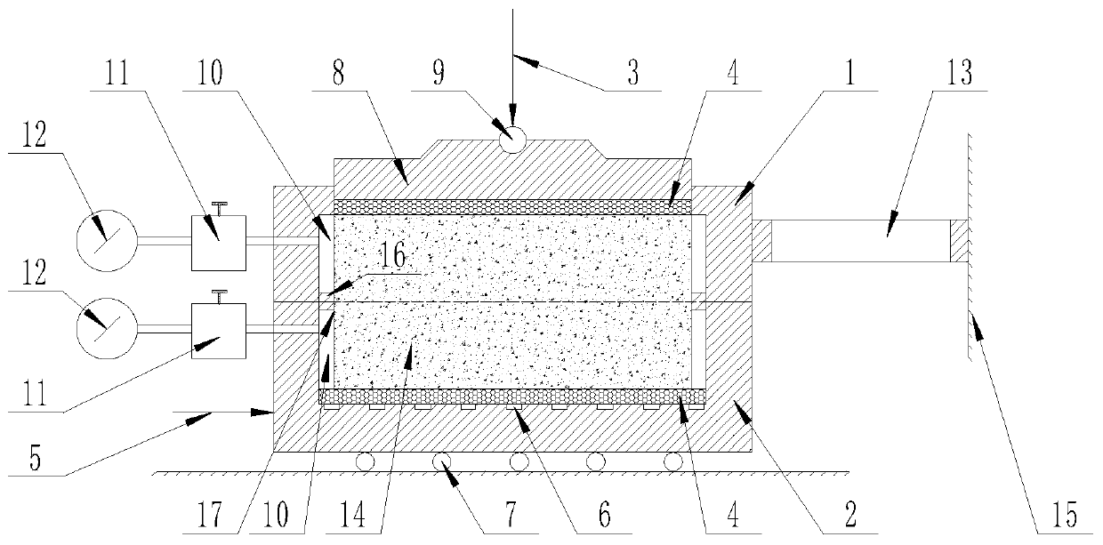
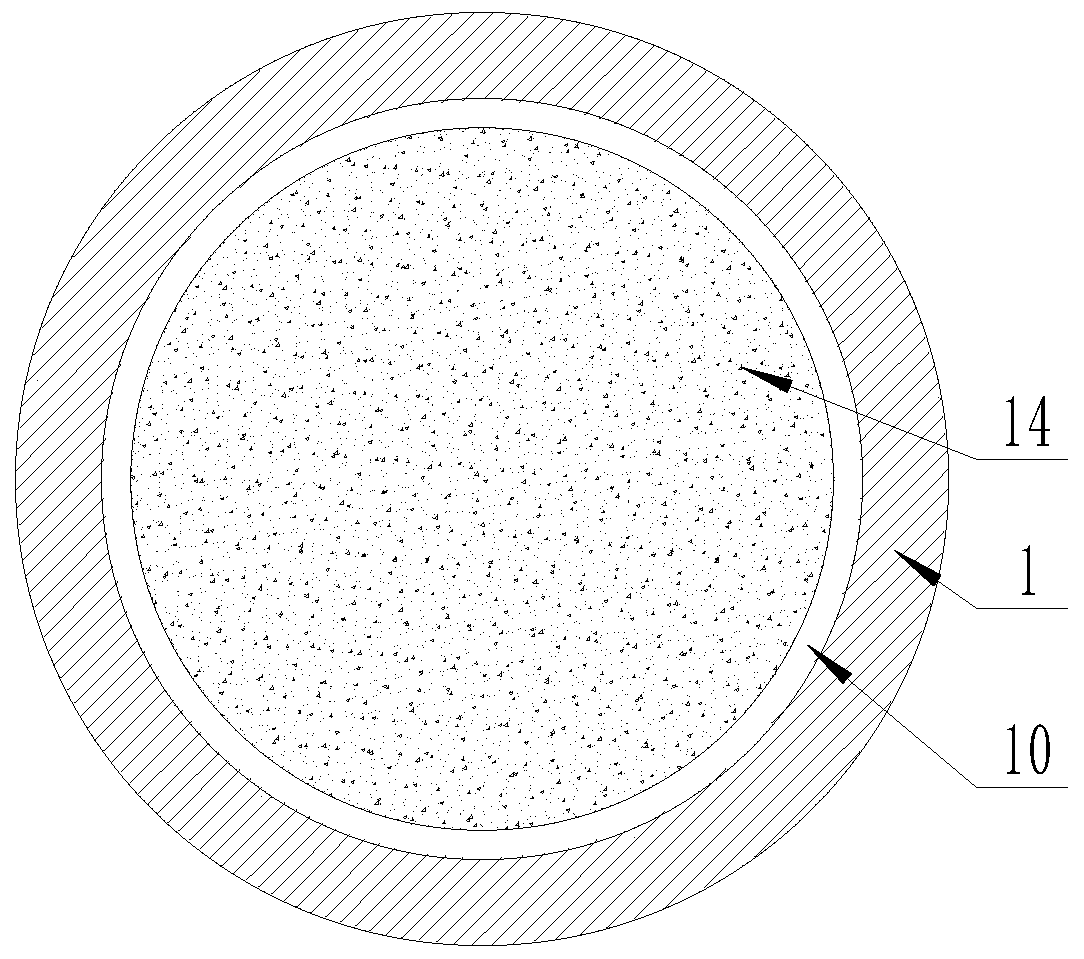
[0044] according to figure 1 and figure 2 A direct shear test device with controllable orthogonal stress state is shown, including

[0045] Cutting box, the cutting box is a circular box body composed of an upper cutting box 1 and a lower cutting box 2 arranged up and down, and a circular cavity is arranged in the cutting box;

[0046] a sliding mechanism, the sliding mechanism is slidingly connected to the lower bottom surface of the lower shear box 2;

[0047] A horizontal loading device 5, which is connected to the outer side wall of the lower shear box 2;

[0048] Fixing device, the fixing device is connected on the outer side wall of the upper shear box 1 opposite to the horizontal loading device 5;

[0049] The vertical loading component 3 is arranged on the top of the upper shear box 1;

[0050] A confining pressure control device connected to the side walls of the upper shear box 1 and the lower shear box 2;

[0051] The water permeable mechanism is arranged in t...

Embodiment 2

[0056] according to figure 1 The shown direct shear test device with controllable orthogonal stress state is different from the first embodiment in that: the water permeable mechanism is two permeable stones 4; one of the permeable stones 4 is arranged on the bottom surface of the lower shear box 2 On the top, another permeable stone 4 is arranged on the lower surface of the vertical loading assembly 3 .

[0057] Preferably described water permeable mechanism also comprises drain hole 6; Described drain hole 9 is blind hole or through hole, is arranged on lower shear box 2 bottom surfaces.

[0058] In actual use, the moisture squeezed out during the drainage and consolidation process of the sample 14 under the original stress state is absorbed by the permeable stone 4, so that the sample 14 can be better and quickly consolidated.

[0059] When the moisture in the sample is not much, only the permeable stone 4 can be used to absorb water. When the moisture contained in the sam...

Embodiment 3

[0062] according to figure 1 The shown direct shear test device with controllable orthogonal stress state is different from the first embodiment in that: the sliding mechanism is composed of multiple pulleys 7; the multiple pulleys 7 are evenly arranged in the lower shear box 2 under the bottom.

[0063] In actual use, the sliding mechanism adopts the technical scheme of a plurality of pulleys 7, which can not only guarantee to meet the requirements of the test, but also save costs. In specific applications, the sliding mechanism can also adopt various methods such as slide rails. Any device can be used as long as it can move the shear box smoothly.


PUM


Abstract

The invention belongs to the technical field of civil engineering, water conservancy and hydropower engineering and new energy engineering, and particularly relates to an orthogonal stress state controllable direct shear test device and test method. The device is formed by organically combining a circular sliding mechanism, a horizontal loading device, a fixing device, a vertical loading assembly,a confining pressure control device and a permeable mechanism, wherein the sliding mechanism is provided with an upper shearing box and a lower shearing box and is connected to the lower part of thelower shearing box. According to the actual stress state of the rock-soil body, the normal pressure and the lateral confining pressure bidirectional stress of the test sample are regulated and controlled, so that the test sample is subjected to drainage consolidation in an original occurrence stress state. The problem that confining pressure regulation cannot be considered in a traditional directshear test device and method is solved, and the real stress state of the sample is restored as much as possible. According to the method, the lateral confining pressure of the sample can be dynamically regulated and controlled, the shear strength parameter of the rock-soil body can be obtained more truly, and more detailed and accurate basis is provided for engineering safety and stability analysis.

Description


Claims


Application Information

Patent Timeline
Owner POWERCHINA XIBEI ENG
Why Eureka
Try Eureka