Optical axis adjusting assembly convenient for adjusting optical path

A technology for adjusting components and optical axes, applied in optical components, optics, installation, etc., can solve the problems of optical path readjustment, low adjustment accuracy, inconvenient adjustment, etc., to improve adjustment accuracy, ensure optical path sealing, simple and reliable structure Effect

Pending Publication Date: 2020-06-05
扬州曙光光电自控有限责任公司
View PDF0 Cites 1 Cited by
  • Summary
  • Abstract
  • Description
  • Claims
  • Application Information

AI Technical Summary

Problems solved by technology

For example, the mirror type, the adjustment accuracy is not high, and the optical axis will change over time, the anti-vibration ability is not strong, and it needs to be installed in the optical path, so the adjustment is inconvenient
[0003] Since the optical axis is generally inside the instrument, it is inconvenient to use the paired optical wedges directly after opening the instrument and then adjusting the optical axis.
In addition, the conventional wedge mirror is adjusted by manually adjusting the wedge mirror. When adjusting the optical path, it is necessary to open the product and turn the wedge mirror directly, which makes it inconvenient to use, and the optical path cannot be sealed, which is easy to bring dust to the surface of the optical parts. In addition, when the energy density is high, the dust is still Can cause damage to optical parts
For large systems, sometimes opening the product will cause the optical path of the entire system to be readjusted

Method used


Image

  • Optical axis adjusting assembly convenient for adjusting optical path
  • Optical axis adjusting assembly convenient for adjusting optical path
  • Optical axis adjusting assembly convenient for adjusting optical path

Examples


Embodiment Construction

[0017] The present invention will be further introduced below in conjunction with the accompanying drawings and specific embodiments.

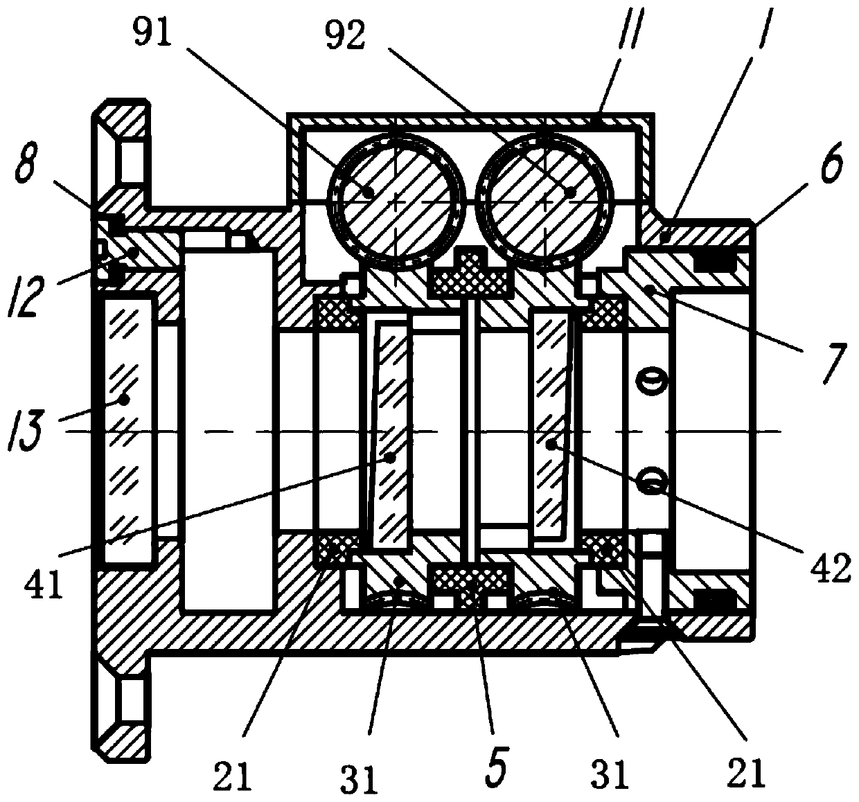
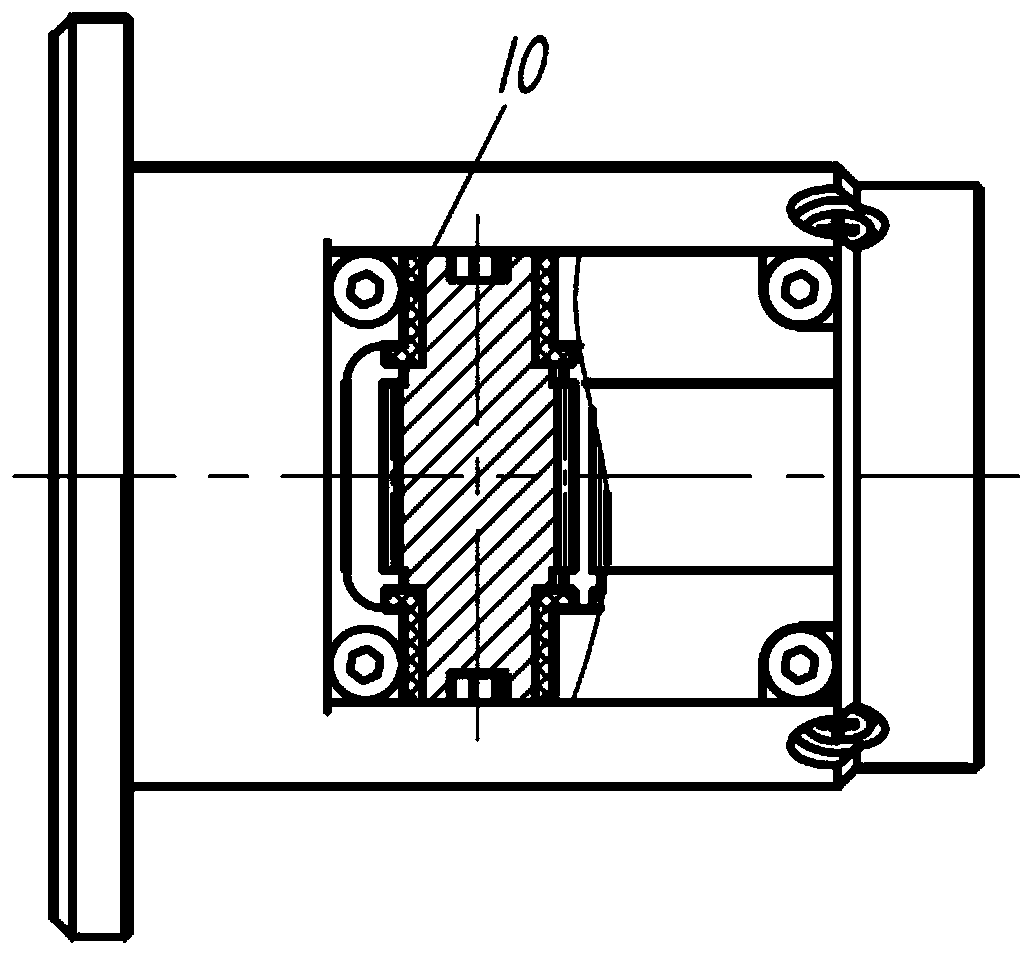
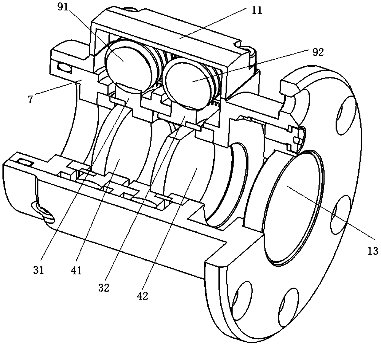
[0018] combine figure 1 , an optical axis adjustment assembly for adjusting the optical path of the present invention, including an optical wedge mount 1, a first worm wheel pressure ring 21, a second worm wheel pressure ring 22, a first worm wheel 31, a second worm wheel 32, a first wedge mirror 41. Second wedge mirror 42, worm wheel spacer 5, worm wheel pressing plate 7, first worm 91, second worm 92, worm pressing plate 11, sealing screw 12, dustproof mirror 13;

[0019] The first wedge mirror 41 is fixed in the center hole of the first turbine 31, and the second wedge mirror 42 is fixed in the center hole of the second turbine 32; between the first wedge mirror 41 and the first turbine 31, the second wedge A ventilation hole is provided between the mirror 42 and the second turbine 32; the first turbine 31 and the second turbine 32 are coa...


PUM


Abstract

The invention discloses an optical axis adjusting assembly convenient for adjusting an optical path. The optical axis adjusting assembly comprises an optical wedge mounting base, two worm wheel pressing rings, two worm wheels, two wedge mirror worm wheel space rings, a worm wheel pressing plate, two worms, a worm pressing plate and a dustproof mirror. The two wedge mirrors are respectively fixed in the central holes of the two turbines; vent holes are formed between the two wedge mirrors and the two turbines; the two turbines are coaxially arranged in the optical wedge mounting base; a worm gear space ring is arranged between the two turbines; the worm wheel pressing rings are respectively arranged on the other sides of the two worm wheels and the second turbine; the worm pressing plate isfixed on the optical wedge mounting base; the two worms and the second turbines are respectively meshed with the two turbines; worm washers sleeve the two ends of the two worms; the dustproof mirroris fixed at one end of the optical wedge mounting base; the worm pressing plate is fixed at the other end of the optical wedge mounting base and provides pre-tightening force; and the excircle of theworm pressing plate and the optical wedge mounting base are sealed. The optical axis inside the instrument can be adjusted from the outside of the instrument, and the requirements for air tightness and impact vibration resistance of the optical path are met.

Description

technical field [0001] The invention belongs to the field of optical path adjustment, in particular to an optical axis adjustment component which is convenient for adjusting the optical path. Background technique [0002] Micro-adjustment of the optical axis in optical instruments is necessary, either with mirrors or wedge mirrors. The optical wedges used in pairs are often used because of their advantages such as convenient adjustment, high precision, and small space occupation. Such as mirror type, the adjustment accuracy is not high, and the optical axis will change over time, the anti-vibration ability is not strong, and it needs to be installed in the optical path, so the adjustment is inconvenient. [0003] Since the optical axis is generally inside the instrument, when using the paired optical wedges directly, the instrument needs to be opened to adjust the optical axis, which is inconvenient to use. In addition, the conventional wedge mirror is adjusted by manually...

Claims


Application Information

Patent Timeline
Patent Type & Authority Applications(China)
IPC IPC(8): G02B7/00G02B7/18
CPCG02B7/00G02B7/1805
Inventor 王颇黄家悦许建孙九林谢林林韩科
Owner 扬州曙光光电自控有限责任公司
Why Eureka
Try Eureka