Hospital bed for medical field

A technology in the field of hospital beds, which is applied in the field of hospital beds, can solve the problems of low cost, lack of popularization, and difficulty in popularization, and achieve the effects of low cost, prevention of secondary injuries, and high practicability

Inactive Publication Date: 2020-06-09
何炳法
View PDF5 Cites 2 Cited by
  • Summary
  • Abstract
  • Description
  • Claims
  • Application Information

AI Technical Summary

Problems solved by technology

[0005] The first type, the transfer bed is composed of a bracket with a walking mechanism on the lower side and a bed board that can move laterally. The movable bed board is generally placed on the hospital bed. Then push the transfer bed for inspection. After arriving at the inspection point, just move the horizontally movable bed board to the inspection table without manual lifting, which is labor-saving, especially for those who have just finished surgery Patients who cannot bend; but this method needs to replace all the beds in the hospital, and the cost is high; it has not been popularized
[0006] The second is to use automatic equipment, such as using a robotic arm to lift the patient, but this method has a high individual cost, and ordinary people do not know how to operate it, so it is not easy to popularize
[0007] These two existing methods cannot be popularized due to cost reasons; therefore, it is very necessary to design a hospital bed that can solve the above-mentioned problems and is relatively low in cost and easy to popularize compared with the two existing technologies

Method used


Image

  • Hospital bed for medical field
  • Hospital bed for medical field
  • Hospital bed for medical field

Examples


Embodiment Construction

[0041] The specific implementation manners of the present invention will be further described in detail below in conjunction with the accompanying drawings and embodiments. The following examples or drawings are used to illustrate the present invention, but not to limit the scope of the present invention.

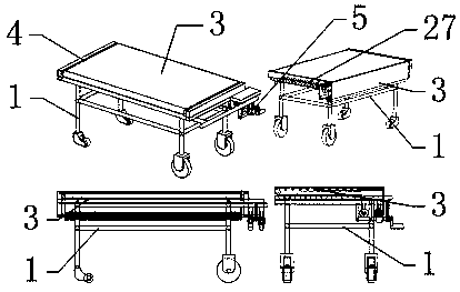
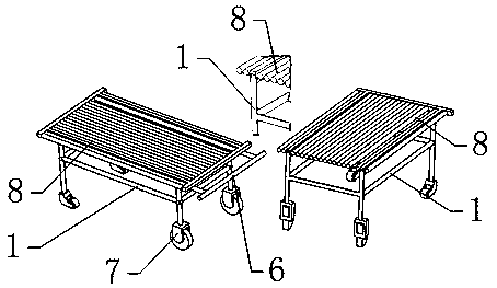
[0042] Such as figure 1 As shown, it includes a frame body 1 and a bed board 8, wherein the lower side of the frame body 1 has a walking mechanism 7, and one end of the frame body 1 has a push rod 6 for the medical staff to push the frame body 1 to walk; the bed board 8 is installed on the frame body 1 It is characterized in that: the upper side of the bed board 8 is installed with a traverse mechanism 3 that drives the patient to laterally traverse.

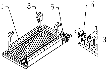
[0043] Such as figure 1 , 2 As shown, the above-mentioned traversing mechanism 3 includes a guide rail 4, an adjustment mechanism 5, a traversing belt 26, a mounting plate 27, a first winding roller 31, and a second windin...


PUM


Abstract

The invention belongs to the technical field of hospital beds, in particular relates to a hospital bed for the medical field. The hospital bed comprises a frame body and a bed board, the hospital bedfacilitates a smaller width of two mounting plates through reasonably designing the width of the two mounting plates, when a patient is transferred from the hospital bed to a hospital bed in an inpatient ward or an examining table, the swing angle of the two mounting plates is smaller so the swaying suffered by the patient is smaller. When the patient is horizontally transferred from a transport bed to a hospital bed in the inpatient ward or the examining table, no relative movement between the hospital bed and the patient occurs when a transverse strap drives the patient to move, separates from the patient and moves, and the secondary injury can be prevented. The rotation of a first winding roller and a second winding roller of the hospital bed is driven by respective worms and gears, therotation of the first winding roller and the second winding roller can be prevented from being affected by pre-loaded pressure of compressing the spring when the worm is not driven to rotate throughthe self-locking function of worms and gears.

Description

[0001] Technical field [0002] The invention belongs to the technical field of sick beds, in particular to a sick bed used in the medical field. Background technique [0003] Patients in the hospital often need to be transferred or checked in various examination rooms on the hospital bed. However, due to the inconvenient movement of the patient, it is often necessary to transfer the patient from the hospital bed to the transfer bed, and push the patient to the check point through the transfer bed. The patient is transferred from the transfer bed to the examination table for inspection. After the inspection is completed, the patient is transferred from the transfer bed to the front of the bed. Finally, the patient is transferred from the transfer bed to the hospital bed. It is very inconvenient to transfer the patient back and forth. The patient needs multiple people to operate during the transfer process. Even if multiple people operate, it is inconvenient to use because the ...

Claims


Application Information

Patent Timeline
IPC IPC(8): A61G1/02A61G1/04A61G1/044A61G7/10
CPCA61G1/02A61G1/04A61G1/044A61G7/1032
Inventor 何炳法
Owner 何炳法
Why Eureka
Try Eureka