Multi-rotor unmanned aerial vehicle control method and device, multi-rotor unmanned aerial vehicle and storage medium

A technology of multi-rotor drones and control methods, applied in the fields of multi-rotor drone control, multi-rotor drones and storage media, can solve problems such as large wind resistance and affecting the flight control effect of multi-rotor drones, and achieve Improve the effect of flight control effects

Active Publication Date: 2020-06-09
SHENYANG WOOZOOM TECH CO LTD
View PDF12 Cites 2 Cited by
  • Summary
  • Abstract
  • Description
  • Claims
  • Application Information

AI Technical Summary

Problems solved by technology

If the attitude angle changes too large and too fast, it will bring greater wind resistance, which will affect the flight control effect of the multi-rotor UAV.

Method used


Image

  • Multi-rotor unmanned aerial vehicle control method and device, multi-rotor unmanned aerial vehicle and storage medium
  • Multi-rotor unmanned aerial vehicle control method and device, multi-rotor unmanned aerial vehicle and storage medium
  • Multi-rotor unmanned aerial vehicle control method and device, multi-rotor unmanned aerial vehicle and storage medium

Examples


Embodiment Construction

[0053] Specific embodiments of the present disclosure will be described in detail below in conjunction with the accompanying drawings. It should be understood that the specific embodiments described here are only used to illustrate and explain the present disclosure, and are not intended to limit the present disclosure.

[0054] It should be noted that the terms "first" and "second" in the specification and claims of the present disclosure and the above drawings are used to distinguish similar objects, and should not be interpreted as describing a specific sequence or sequence.

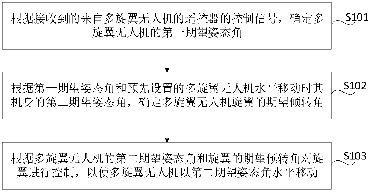
[0055] figure 1 It is a flow chart of a method for controlling a multi-rotor drone according to an exemplary embodiment of the present disclosure. The method is applied to a multi-rotor drone and can be implemented by a built-in controller in the multi-rotor drone. Such as figure 1 As shown, the method includes the following steps:

[0056] S101. Determine a first desired attitude angle of the mult...


PUM


Abstract

The invention relates to a multi-rotor unmanned aerial vehicle control method and device, a multi-rotor unmanned aerial vehicle and a storage medium, and aims to solve the problem of relatively largewind resistance caused by too large and too fast change of the attitude angle of the multi-rotor unmanned aerial vehicle required for meeting relatively high moving speed in related technologies. Themethod is applied to the multi-rotor unmanned aerial vehicle and comprises the following steps: determining a first expected attitude angle of the multi-rotor unmanned aerial vehicle according to a received control signal from the remote controller of the multi-rotor unmanned aerial vehicle; determining an expected tilt angle of the rotors of the multi-rotor unmanned aerial vehicle according to the first expected attitude angle and a preset second expected attitude angle of horizontal movement of the multi-rotor unmanned aerial vehicle, the second expected attitude angle being smaller than thefirst expected attitude angle; and controlling the rotors according to the second expected attitude angle and the expected tilt angle so that the multi-rotor unmanned aerial vehicle horizontally moves at the second expected attitude angle.

Description

technical field [0001] The present disclosure relates to the technical field of unmanned aerial vehicles, and in particular, relates to a control method and device for a multi-rotor unmanned aerial vehicle, a multi-rotor unmanned aerial vehicle and a storage medium. Background technique [0002] Unmanned aerial vehicle (Unmanned Aerial Vehicle, UAV for short), is a kind of unmanned aircraft. UAVs are widely used and are often used in plant protection, urban management, geology, meteorology, electric power, emergency rescue and disaster relief, video shooting and other industries. [0003] In the related art, the displacement motion control of the multi-rotor UAV is to change the attitude angle of the multi-rotor UAV by adjusting the speed of each rotor of the multi-rotor UAV, and through the speed difference between the rotors. When it is not zero, the pulling force generated by the rotor rotation is decomposed orthogonally into a component force parallel to the vertical pl...

Claims


Application Information

Patent Timeline
Patent Type & Authority Applications(China)
IPC IPC(8): G05D1/08G05D1/10
CPCG05D1/0808G05D1/101
Inventor 苏烨李天博梅森齐欣宋大雷
Owner SHENYANG WOOZOOM TECH CO LTD
Why Eureka
Try Eureka