
Wing plate for post-stall manipulation control of airplane

A wing plate and wing technology, which is applied in the aerospace field, can solve the problems of insufficient stability of the aircraft, failure of the steering surface, and reduced control ability, so as to achieve good conventional aerodynamic performance, realize control, increase instability and unsteadiness sexual effect

Inactive Publication Date: 2012-09-26
NORTHWESTERN POLYTECHNICAL UNIV
View PDF0 Cites 0 Cited by
  • Summary
  • Abstract
  • Description
  • Claims
  • Application Information

AI Technical Summary

Problems solved by technology

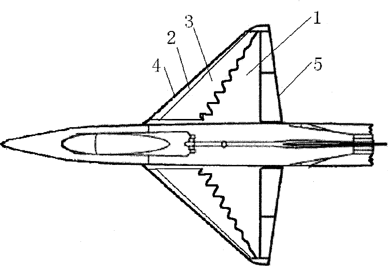
[0008] In order to overcome the deficiencies in the prior art that the control rudder surface fails in the super-maneuvering state, the control ability of the aircraft under the maneuvering flight of the stall is reduced, and the stability of the aircraft is insufficient under the stall angle of attack, the present invention proposes a method for the aircraft to pass the stall. Steering Control Wings

Method used


Image

  • Wing plate for post-stall manipulation control of airplane
  • Wing plate for post-stall manipulation control of airplane
  • Wing plate for post-stall manipulation control of airplane

Examples


Embodiment 1

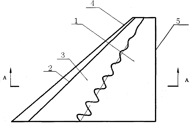
[0033] This embodiment is a wing plate used for post-stall maneuvering control of an aircraft, including a wing 1 , a separation vortex control wing plate rotating shaft 2 and a separation vortex control wing plate 3 .

[0034]Wing 1 is trapezoidal, its root-chord ratio λ is 6; wing sweep angle α is 50°, wing span length b is 4390mm, root chord length C is 6282mm; wing airfoil is selected as NACA0006. Separate vortex control wing plates 3 are symmetrically installed on the upper surfaces of the wings 1 on both sides; this embodiment is described by taking one wing of an aircraft as an example.

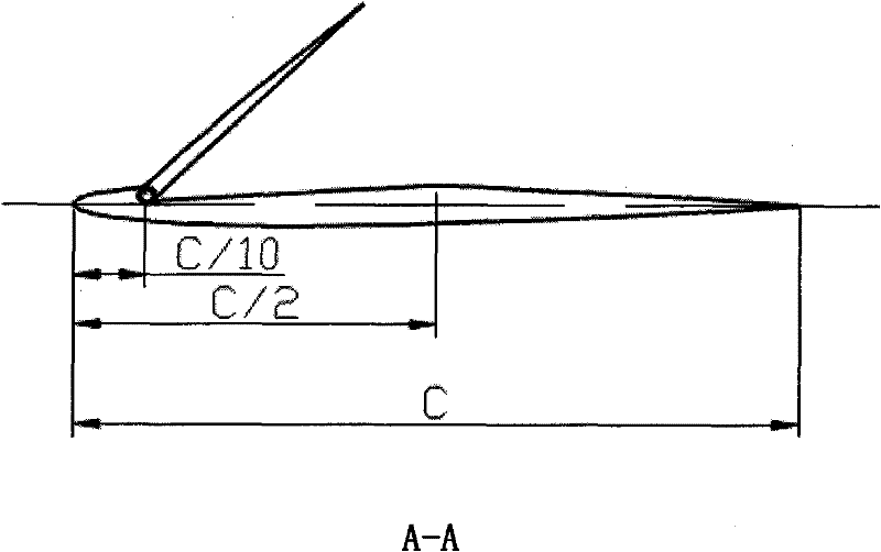
[0035] Such as image 3 shown. On the upper surface of the wings 1 on both sides, from the 10% chord length of the leading edge of the wing 1 to the 50% of the leading edge of the wing 1, there is a concave surface for the installation of the separation vortex control wing plate 3, and the concave surface is an inclined plane along the chord direction; The depth of the concave surfac...

Embodiment 2

[0047] The present embodiment is a wing plate used for aircraft post-stall maneuvering control, which is used for a light aircraft and includes a wing 1 , a separation vortex control wing plate rotating shaft 2 and a separation vortex control wing plate 3 .

[0048] Wing 1 is trapezoidal, its root-chord ratio λ is 5; wing sweep angle α is 45°, wing span length b is 3000mm, root chord length C is 3750mm; wing airfoil is selected as NACA0009. Separate vortex control wing plates 3 are symmetrically installed on the upper surfaces of the wings 1 on both sides; this embodiment is described by taking one wing of an aircraft as an example.

[0049] Such as image 3 shown. On the upper surface of the wings 1 on both sides, from the 10% chord length of the leading edge of the wing 1 to the 50% of the leading edge of the wing 1, there is a concave surface for the installation of the separation vortex control wing plate 3, and the concave surface is an inclined plane along the chord dir...

Embodiment 3

[0061] This embodiment is a wing plate used for the maneuvering control of the aircraft after a stall, including a wing 1 , a separation vortex control wing plate rotating shaft 2 and a separation vortex control wing plate 3 .

[0062] Wing 1 is trapezoidal, its root-chord ratio λ is 7; wing sweep angle α is 45°, wing span length b is 4500mm, root chord length C is 5250mm; wing airfoil is selected as NACA0012. Separate vortex control wing plates 3 are symmetrically installed on the upper surfaces of the wings 1 on both sides; this embodiment is described by taking one wing of an aircraft as an example.

[0063] Such as image 3 As shown, on the upper surface of the wings 1 on both sides, from the 10% chord length of the leading edge of the wing 1 to the 50% of the leading edge of the wing 1, there is a concave surface for the installation of the separation vortex control wing plate 3, and the concave surface is along the chord direction. Inclined surface: The depth of the con...


PUM


Abstract

The invention relates to a wing plate for the post-stall manipulation control of an airplane, comprising a separation vortex control wing plate rotating shaft and a separation vortex control wing plate. The basic shape of the separation vortex control wing plate is trapezoid, and the shape of the upper surface of the separation vortex control wing plate is the same as that of the upper surface ofa matched wing, and the separation vortex control wing is fixed in the concave surface on the upper surface of the wing and form a complete wing section surface together with the upper surface of thewing. The bevel edge of the rear edge of the separation vortex control wing is in a wave shape, and the total period number N of a wave line is 6-8. The front edge of the separation vortex control wing plate is located at a position 10 percent of local chord length of the wing, and the width of the separation vortex control wing plate along the chordwise direction of the wing is 40 percent of thelocal chord length of the wing. The separation vortex control wing plate is matched with the separation vortex control wing plate rotating shaft, and the separation vortex control wing plate is controlled to be opened or closed through a telex control mechanism. When the airplane is in post-stall maneuver flight, the separation vortex control wing plate is opened to restrain the instability and non-stationarity of wing wake flow, thereby the airplane is controlled under the condition of post-stall flight.

Description

technical field [0001] The invention relates to the field of aerospace and space, and relates to a wing plate used for the maneuvering control of an aircraft after a stall. Background technique [0002] Modern fighters use a large number of guided weapons, and the guided weapons are locked by airborne radars. Therefore, it is an element of offense and defense to bring the opponent into the radar field of view of the opponent as soon as possible or escape from the radar field of view of the opponent as soon as possible. If the aircraft can only fly under normal conditions, it will take a long time to complete both turning and climbing, which is not conducive to the locking and anti-locking of the airborne radar. Therefore, in close-range air combat, quickly aiming at the enemy plane and keeping yourself out of the opponent's sight, that is, quickly attacking the enemy under the premise of effectively preserving yourself, has become the most important combat quality of modern ...

Claims


Application Information

Patent Timeline
Patent Type & Authority Patents(China)
IPC IPC(8): B64C3/38
Inventor 蔡晋生孟宣市李文丰
Owner NORTHWESTERN POLYTECHNICAL UNIV
Learn More