Electronic wire connecting device with anti-falling function

A technology for connecting devices and electronic wires, which is applied to the components, connections, coupling devices and other directions of connecting devices, can solve problems such as inconvenient operation, and achieve the effects of convenient operation and improved fixing effect.

Inactive Publication Date: 2020-06-09
章军伟
View PDF8 Cites 2 Cited by
  • Summary
  • Abstract
  • Description
  • Claims
  • Application Information

AI Technical Summary

Problems solved by technology

[0005] However, in the above-mentioned patent, there are multiple wire body anti-shedding structures corresponding to the positions of multiple electronic wires, but the multiple wire body anti-shedding structures are

Method used


Image

  • Electronic wire connecting device with anti-falling function
  • Electronic wire connecting device with anti-falling function
  • Electronic wire connecting device with anti-falling function

Examples


Example Embodiment

[0026] Example one

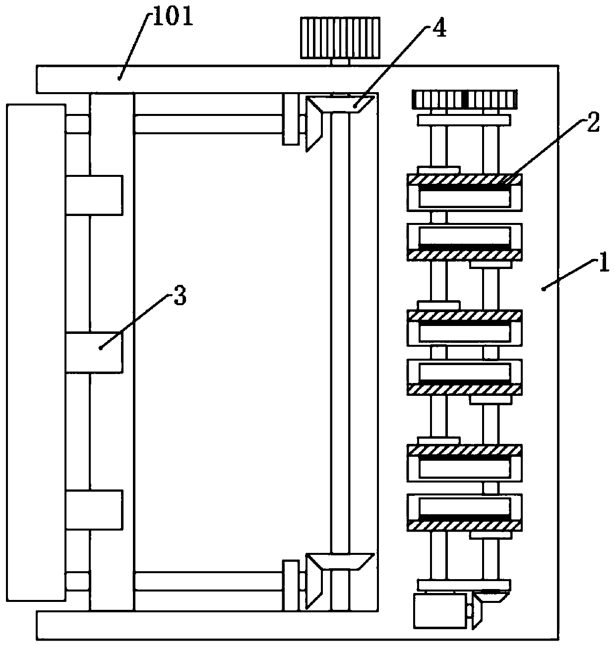
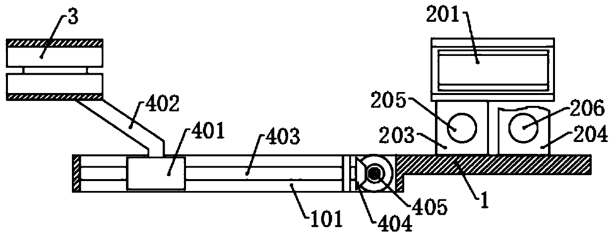
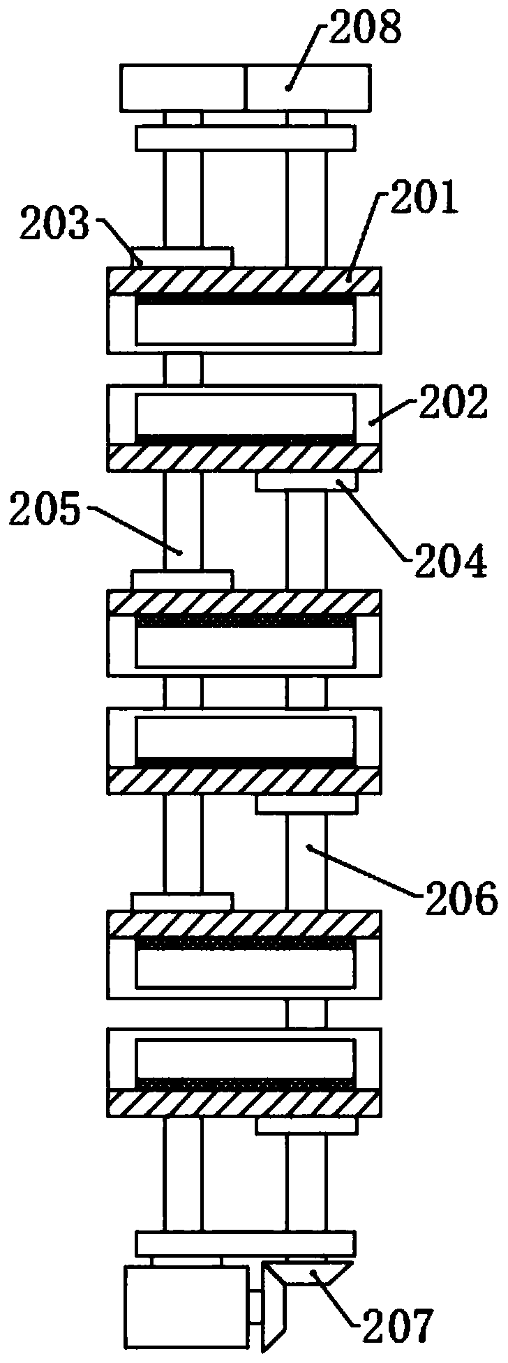
[0027] Please refer to the drawings, the present invention provides a technical solution: an electronic wire connection device with anti-dropping function, comprising a fixing table 1, a fixing assembly 2 is arranged on the top surface of the fixing table 1, and the left side of the fixing table 1 is symmetrically fixed There are two side plates 101, and a limiting component 3 is arranged between the two side plates 101; the fixing component 2 includes a plurality of first splints 201 and second splints 202 evenly and spaced apart, and the first splint 201 and the second splint The splints 202 are all circular arc plates, the first slider 203 is fixed on the left side of the bottom of the plurality of first splints 201, the first screw rod 205 is sleeved in the first slider 203, and the bottom of the plurality of second splints 202 A second sliding block 204 is fixed on the right side, and a second screw rod 206 is sleeved on the multiple second sliding block...

Example Embodiment

[0034] Example two

[0035] The structure of this embodiment is basically the same as that of the first embodiment. The difference is that an adjustment assembly 4 is provided under the limit assembly 3, and the adjustment assembly 4 is connected to the side plate 101 correspondingly. The adjustment assembly 4 includes sliding connection on both sides The adjustment plate 401 between the plates 101, the top surface of the adjustment plate 401 is uniformly fixed with a plurality of inclined connecting rods 402, the top of the connecting rod 402 is fixedly connected with the lower splint 301, the two sides of the adjusting plate 401 are screwed with screws 403, The screw 403 is rotatably connected with the side plate 101, and the right end is fixed with a third bevel gear 404, a rotating shaft 405 is rotatably connected between the right ends of the two side plates 101, and one end of the rotating shaft 405 is fixed with a rotating handle, and A plurality of fourth bevel gears are ...


PUM


Abstract

The invention discloses an electronic wire connecting device with an anti-falling function in the technical field of electronic wire connection. The device comprises a fixing table, a fixing assemblyis arranged on the top surface of the fixing table, two side plates are symmetrically fixed to the left side of the fixing table, a limiting assembly is arranged between the two side plates, the fixing assembly comprises a plurality of first clamping plates and a plurality of second clamping plates, and the first clamping plates and the second clamping plates are evenly arranged at intervals. Electronic wires are placed in the limiting grooves in the fixing assembly, the electronic wires are limited in the limiting grooves under the action of the spring, the upper clamping plates and the lowerclamping plates, and therefore the positions of connectors of the electronic wires are limited through the limiting assembly, and a certain supporting effect is provided; the right side section of the electronic wire is placed between the first clamping plate and the second clamping plate at the corresponding positions, a first lead screw and a second lead screw are rotated through the motor, a first sliding block and a second sliding block move to drive the first clamping plate and the second clamping plate to get close to each other, the electronic wire is fixed, and the fixing effect of the electronic wire is improved.

Description

technical field [0001] The invention relates to the technical field of electronic wire connection, in particular to an electronic wire connection device with a fall-off prevention function. Background technique [0002] Electronic wire is an abbreviation for the internal wire of electrical equipment. The electrification is mainly based on weak current, which is different from the cable in the strong current category. The electronic wires on the market are divided into UL standard, 3C standard, and VDE standard 3 For a series of wires, the AWG unit is generally UL standard, and the square unit is generally 3C standard or VDE standard. Domestic electronic wire manufacturers mainly use 3C and UL standards. [0003] The electronic wire is the basic structure for the connection between various electrical appliances and lines. In the wiring connection process of electrical equipment, a special electronic wire connection device is needed to assist the wiring. However, the tradition...

Claims


Application Information

Patent Timeline
IPC IPC(8): H01R13/56H01R13/639H02G3/04
CPCH01R13/56H01R13/639H02G3/045
Inventor 章军伟
Owner 章军伟
Why Eureka
Try Eureka