Buckle type cable explosion-proof box

A snap-on, explosion-proof box technology, applied in cable joints and other directions, can solve the problems of troublesome disassembly, time-consuming installation, corrosion and rust of bolts, etc., and achieves the effect of convenient disassembly, saving construction time and reducing construction amount.

Active Publication Date: 2020-06-09
STATE GRID HUNAN ELECTRIC POWER +2
5 Cites 0 Cited by

AI-Extracted Technical Summary

Problems solved by technology

[0003] At present, the mainstream cable explosion-proof box on the market, the cable explosion-proof box is spliced ​​together by fastening two halves of the box with bolts, and multiple fastening screws are used to fix the connection. Due to the fact that multiple screws need to be tightened during actual in...

Method used

As shown in Figure 2, buckle-type connection fittings 2 comprise two connecting crossbeams 23, and two connecting crossbeams 23 are arranged in parallel, so that two connecting crossbeams 23 pass through the first vertical beam 21 respectively and connect with the second vertical beam The beams 22 are connected to form a quadrilateral structure, through which the structure can be combined with the design of the first box body 11 and the second box body 12 to realize firm fixing between the first box body 11 and the second box body 12 .
In order to improve the connection firmness of connecting beam 23 and the first vertical beam 21, as shown in Figure 2, in the present embodiment, the first vertical beam 21 is...

Abstract

The invention discloses a buckle type cable explosion-proof box. The explosion-proof box comprises an explosion-proof box body formed by assembling a first box body and a second box body, wherein a buckle type connecting fitting is arranged between the first box body and the second box body, the buckle type connecting fitting comprises a first vertical beam, a second vertical beam and a connectingcross beam, the first vertical beam is fixed to the first box body, the second vertical beam is fixed to the second box body and is parallel to the first vertical beam, and the connecting cross beampenetrates through the first vertical beam and then is connected with the second vertical beam to connect the first box body and the second box body into a whole. According to the invention, installation and fastening of the explosion-proof box can be realized conveniently, the size of the fitting can be designed according to the specification of an actual cable explosion-proof box through the buckle type structure, the explosion-proof box can adapt to a fastening problem of explosion-proof boxes of multiple specifications, a traditional bolt structure is replaced with the buckle type explosion-proof box structure, the mounting and dismounting are very convenient, the construction amount can be reduced, the construction time can be saved, and the mounting and dismounting efficiency can beimproved.

Application Domain

Cable junctions

Technology Topic

Structural engineeringElectric cables

Image

  • Buckle type cable explosion-proof box
  • Buckle type cable explosion-proof box
  • Buckle type cable explosion-proof box

Examples

  • Experimental program(1)

Example Embodiment

[0022] The implementation of the present invention will be described in detail below with reference to the drawings.
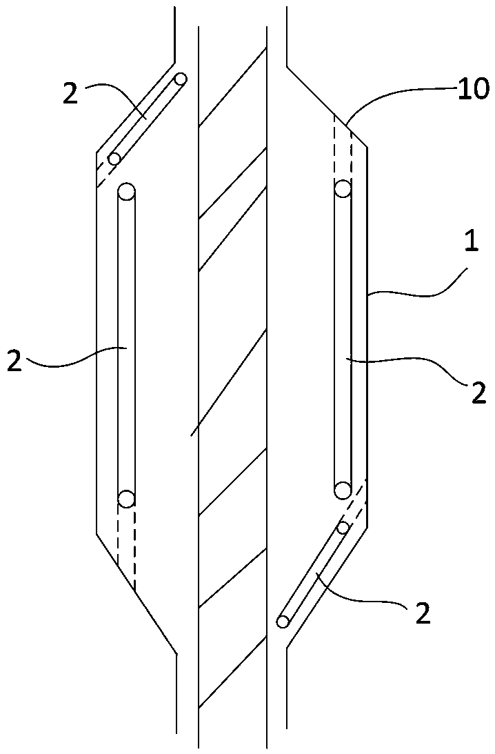
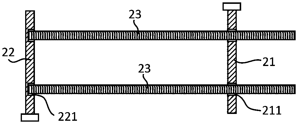
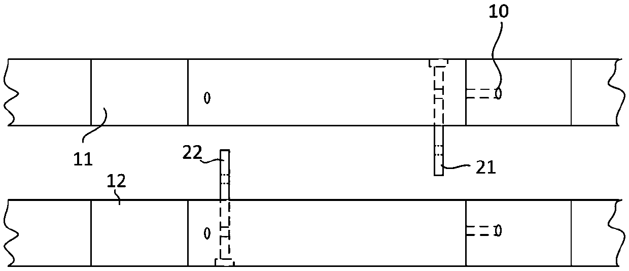
[0023] Such as figure 1 , figure 2 with image 3 As shown, the buckle-type cable explosion-proof box of this embodiment includes an explosion-proof box body 1 composed of a first box body 11 and a second box body 12, and a card is provided between the first box body 11 and the second box body 12. The buckle-type connection fitting 2 includes a first vertical beam 21, a second vertical beam 22 and a connecting beam 23. The first vertical beam 21 is fixed to the first box body 11, and the second vertical beam 22 is fixed to The second box body 12 is arranged in parallel with the first vertical beam 21, and the connecting beam 23 passes through the first vertical beam 21 and is connected to the second vertical beam 22 to connect the first box body 11 and the second box body 12 into one body. When installing and tightening the buckle-type cable explosion-proof box, the connecting beam 23 is inserted into the explosion-proof box body 1 and connected to the second vertical beam 22 after passing through the first vertical beam 21 to realize the fastening of the explosion-proof box. The operation is simple.
[0024] Among them, the first box body 11 and the second box body 12 can choose a variety of materials, such as stainless steel, glass fiber reinforced plastic, epoxy resin, etc., which can be selected according to actual application scenarios.
[0025] Such as figure 1 with image 3 As shown, the snap-fit ​​connection fitting 2 is provided inside the explosion-proof box body 1, and the outer wall of the explosion-proof box body 1 is provided with a mounting hole 10 for inserting and installing the connecting beam 23.
[0026] Such as figure 1 As shown, the middle part of the explosion-proof box body 1 in this embodiment is provided with trapezoidal protrusions protruding laterally to both sides, and the two trapezoidal protrusions are arranged symmetrically. In order to achieve a firm connection between the first box body 11 and the second box body 12, such as figure 1 As shown, the top edges of the two trapezoidal protrusions in this embodiment ( figure 1 The middle is the left and right sides) are installed with snap-on connection fittings 2, and a pair of beveled edges ( figure 1 The center is a pair of hypotenuses in the upper left corner and the lower right corner) are installed with snap-on connection fittings 2. The height of the first vertical beam 21 and the second vertical beam 22 is designed according to the thickness of the explosion-proof box body 1 in actual use, and the length of the connecting beam 23 is designed according to the edge width of the explosion-proof box body 1 in actual use.
[0027] In order to improve the connection firmness of the connecting beam 23 and the first vertical beam 21, such as figure 2 As shown, in this embodiment, the first vertical beam 21 is provided with a threaded through hole 211, and the connecting beam 23 passes through the threaded through hole 211 of the first vertical beam 21 and is threadedly fitted with the threaded through hole 211, so that the connecting beam 23 It is firmly connected with the first vertical beam 21.
[0028] In order to facilitate the determination of the connection stroke of the connecting beam 23, such as figure 2 As shown, the second vertical beam 22 is provided with a threaded blind hole 221, and the end of the connecting beam 23 is threadedly fitted with the threaded blind hole 221.
[0029] Such as figure 2 As shown, the snap-fit ​​connection fitting 2 includes two connecting beams 23, and the two connecting beams 23 are arranged in parallel, so that the two connecting beams 23 respectively pass through the first vertical beam 21 and are connected to the second vertical beam 22 to form a quadrilateral structure By combining the design of the first box body 11 and the second box body 12 with this structure, the first box body 11 and the second box body 12 can be firmly fixed.
[0030] Compared with the traditional bolt fastening method, the snap-on cable explosion-proof box of this embodiment is easy to operate and greatly saves construction time. The use of the snap-type cable explosion-proof box of this embodiment can effectively improve the installation efficiency of the cable explosion-proof box and provide a convenient method for on-site installation of the cable explosion-proof box.
[0031] The above are only the preferred embodiments of the present invention, and the protection scope of the present invention is not limited to the above-mentioned embodiments. All technical solutions under the idea of ​​the present invention belong to the protection scope of the present invention. It should be pointed out that for those of ordinary skill in the art, several improvements and modifications made without departing from the principles of the present invention should also be regarded as the protection scope of the present invention.

PUM

no PUM

Description & Claims & Application Information

We can also present the details of the Description, Claims and Application information to help users get a comprehensive understanding of the technical details of the patent, such as background art, summary of invention, brief description of drawings, description of embodiments, and other original content. On the other hand, users can also determine the specific scope of protection of the technology through the list of claims; as well as understand the changes in the life cycle of the technology with the presentation of the patent timeline. Login to view more.

Similar technology patents

Eye moistening spectacles

Owner:GUANGZHOU YOUDEQING BIOTECH

Combined disk bracket

ActiveCN103853272AEasy to disassemble
Owner:HUAWEI DEVICE CO LTD

Classification and recommendation of technical efficacy words

  • Reduce the amount of construction
  • Easy to disassemble

Cable tunnel positioning and broadcasting system employing VLC-PLC technologies

InactiveCN105141343AHigh-speed and reliable positioning and broadcastingReduce the amount of construction
Owner:STATE GRID HEBEI ENERGY TECH SERVICE CO LTD +2

Sliding track vehicle for dragging and launching drilling ship

InactiveCN103738484Alow costReduce the amount of construction
Owner:上海中远船务工程有限公司

Separated type tunnel arch-replacement supporting structure and construction method thereof

PendingCN108561156AReduce the amount of constructionavoid safety hazards
Owner:ANHUI HIGHWAY BRIDGE ENG CO LTD

Mooring system of floating type floating island

PendingCN108128410ALighten the mooring loadReduce the amount of construction
Owner:盛和众诚(北京)新能源科技有限公司

Novel ceiling mounting structure

Owner:上海西蒙铝业有限公司

Fire-fighting alternating current smoke detector device

InactiveCN106683321AReduce electric shock accidentsEasy to disassemble
Owner:泰州英格伟精密机械有限公司

Inspection robot for underground coal mine

Owner:安徽玄离智能科技股份有限公司
Why Eureka
Try Eureka