A screw thread layer glue injection machine

A technology of glue injection machine and bolts, which is applied in the direction of coating, the device for coating liquid on the surface, etc., can solve the problems of no significant improvement in glue injection efficiency, inability to realize automatic batch glue injection device, etc., to improve production. The effect of efficiency

Active Publication Date: 2021-09-17
罗若娜
View PDF5 Cites 0 Cited by
  • Summary
  • Abstract
  • Description
  • Claims
  • Application Information

AI Technical Summary

Problems solved by technology

[0004] In order to overcome the fact that most of the glue injection machines on the market are manually injecting glue to the bolts, automatic batch glue injection devices cannot be realized, and the glue injection efficiency has not been significantly improved.

Method used


Image

  • A screw thread layer glue injection machine
  • A screw thread layer glue injection machine
  • A screw thread layer glue injection machine

Examples


Embodiment 1

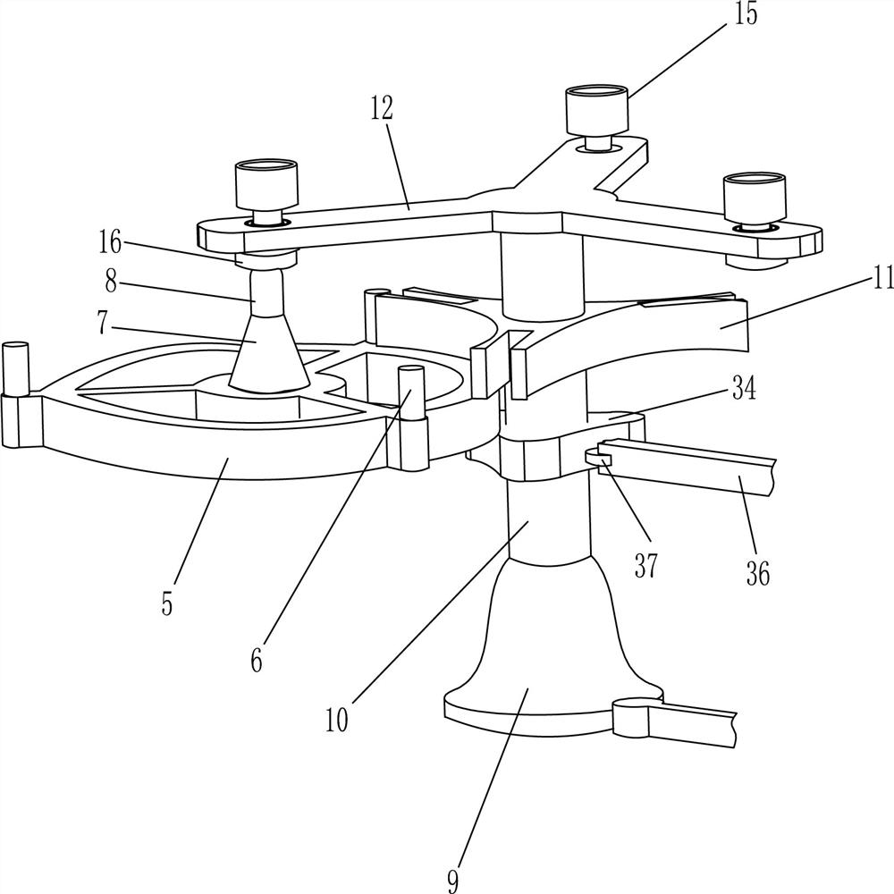
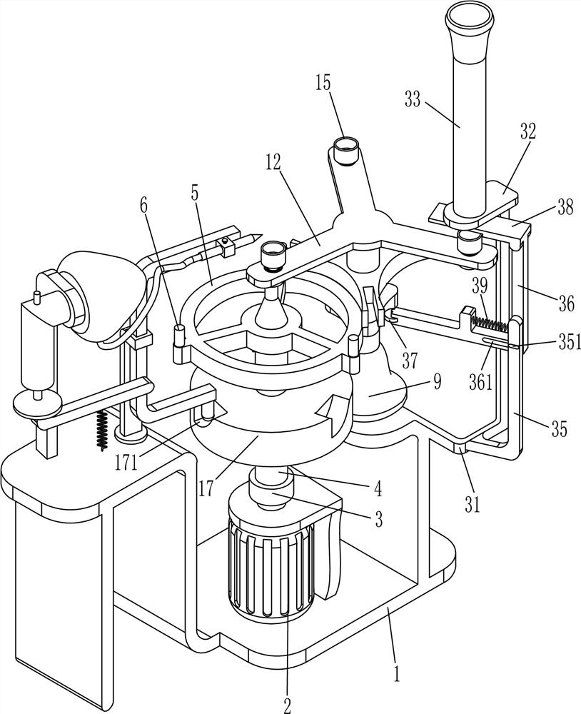
[0021] A bolt thread layer glue injection machine, such as Figure 1-3 As shown, it includes a frame 1, a motor 2, a coupling 3, a first shaft 4, a ring frame 5, a cylinder 6, a tapered seat 7, an iron column 8, a bearing seat 9, a second shaft 10, and a grooved plate 11. Triangular plate 12, ball bearing 13, third rotating shaft 14, cap 15, magnet 16 and glue injection device, motor 2 is fixedly connected to the upper side of the middle part of frame 1, and motor 2 is located in the recessed part of frame 1. 2 is vertically connected with the first rotating shaft 4 through the coupling 3, the upper part of the first rotating shaft 4 is fixedly connected with the ring frame 5, and the upper side of the ring frame 5 is respectively equipped with three columns 6, and the three columns 6 are arranged equidistantly, The upper middle part of the ring frame 5 is fixedly connected with a conical seat 7, the upper end of the conical seat 7 is equipped with an iron column 8, and the po...

Embodiment 2

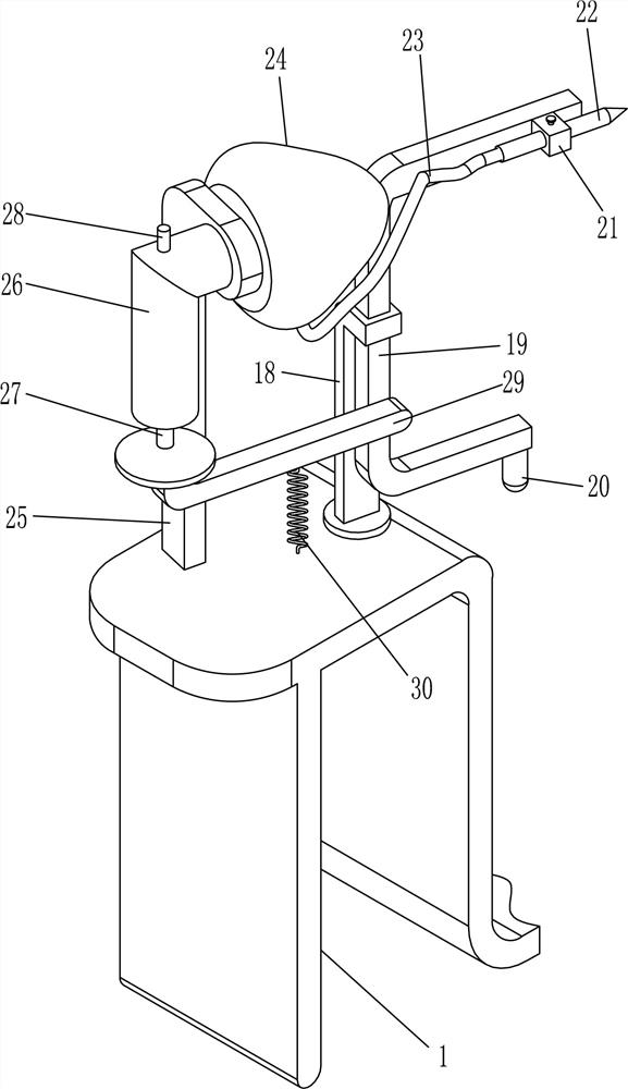
[0024] On the basis of Example 1, such as figure 1 and Figure 4 As shown, it also includes a track disc 17, a sleeved pole 18, a slide bar 19, a universal ball 20, a ferrule 21, a glue injection head 22, a hose 23 and a glue pot 24, and the first rotating shaft 4 is covered with a track Disc 17, orbital disc 17 is positioned at the right below of ring frame 5, and three equidistant gaps 171 are annularly opened on orbital disc 17, and band cover strut 18 is installed on the upper side of frame 1 left platform, band sleeve strut 18 Located at a position close to the track disc 17, the front side of the upper end of the strut with sleeve 18 is slidably connected with a slide bar 19, which can slide up and down along the strut with sleeve 18, and the lower end of the slide bar 19 is fixedly connected with a universal ball 20 , the universal ball 20 is in contact with the notch 171 on the track disk 17, and a ferrule 21 is installed on the front side of the other end of the slid...

Embodiment 3

[0027] On the basis of Example 2, such as Figure 4 and Figure 5 As shown, the glue injection device includes a first bracket 25, a cylinder body 26, a push rod 27, a piston 271, a one-way valve 28, a connecting rod 29 and a tension spring 30. A support 25, the first support 25 is fixedly connected with a cylinder 26, the cylinder 26 is provided with a piston 271, the side of the piston 271 is in close contact with the inner wall of the cylinder 26, the piston 271 can move up and down in the cylinder 26, the cylinder The upper wall of 26 is provided with one-way valve 28, and when piston 271 moves downwards, air can flow into cylinder body 26 through one-way valve 28, and slide bar 19 front side middle parts are fixedly connected with connecting rod 29, and connecting rod 29 is positioned at band cover support. Below the sliding sleeve on the rod 18, one end of the connecting rod 29 is fixedly connected to the push rod 27, the push rod 27 is located on the upper side of the ...


PUM


Abstract

The invention relates to a glue injection device for mechanical parts, in particular to a bolt thread layer glue injection machine. The technical problem to be solved is how to provide a bolt thread layer glue injection machine that can quickly inject glue to the bolts and can fix the bolts during the glue injection. A screw thread layer glue injection machine includes a frame, a motor, a shaft coupling, a first rotating shaft, a ring frame, a cylinder, a tapered seat, etc.; The shaft device is connected with the first rotating shaft, and the upper part of the first rotating shaft is fixedly connected with a ring frame, and the upper side of the ring frame is respectively fixed with three columns, and the upper middle part of the ring frame is fixedly connected with a tapered seat. The invention only needs the operator to turn on the motor and put the bolts into the bolt barrel, then the bolts can be automatically injected with glue, and the bolts can be adsorbed and fixed during the glue injection.

Description

technical field [0001] The invention relates to a glue injection device for mechanical parts, in particular to a bolt thread layer glue injection machine. Background technique [0002] A bolt is a mechanical part, a cylindrical threaded fastener with a nut, a type of fastener consisting of a head and a screw, which needs to be matched with a nut to fasten and connect two hole parts. Surface treatment is often carried out during processing to ensure that the product can be stored for a long time without being oxidized. Such products are usually coated, that is, a layer of protective film is coated on the surface of the product so that the product does not directly contact the outside world and is not easily corroded. At present, most of the glue injection machines on the market inject glue to the bolts manually, and cannot realize automatic batch glue injection devices, and the glue injection efficiency has not been significantly improved. In order to reduce the cost of gl...

Claims


Application Information

Patent Timeline
Patent Type & Authority Patents(China)
IPC IPC(8): B05C5/02B05C13/02
CPCB05C5/0212B05C13/02
Inventor 罗若娜陈小芳
Owner 罗若娜
Why Eureka
Try Eureka