Glue filling system for large heliostat

A heliostat and glue-filling technology, which is applied in the direction of material gluing, connecting components, coating, etc., can solve the problem of inconvenient access for people

Active Publication Date: 2021-09-14
东方电气集团科学技术研究院有限公司 +1
View PDF0 Cites 0 Cited by
  • Summary
  • Abstract
  • Description
  • Claims
  • Application Information

AI Technical Summary

Problems solved by technology

Due to the large size of the heliostat, there are many holes involved in the glue filling of a single heliostat, and it is inconvenient for people to reach it. Therefo

Method used


Image

  • Glue filling system for large heliostat
  • Glue filling system for large heliostat
  • Glue filling system for large heliostat

Examples


Embodiment 1

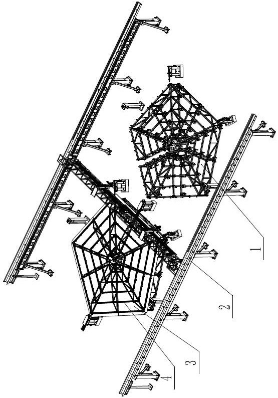
[0041] As shown in the figure, a large-scale heliostat glue filling system includes a curvature adjustment platform 1 and a gantry glue injection system 2. There are at least two curvature adjustment platforms 1, and the two curvature adjustment platforms 1 are respectively installed on the gantry glue injection system. 2, the assembly, positioning and automatic glue filling and curing of the heliostat mirror surface 3 and the heliostat steel structure 4 can be realized. In order to improve the efficiency of gantry glue injection and reduce waiting time, one gantry glue injection system 2 can cover two or more curvature adjustment platforms 1 .

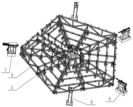
[0042] The curvature adjustment platform 1 includes a mirror curvature adjustment platform 6, a steel structure positioning platform 5, a steel structure auxiliary positioning mechanism 7, a positioning column 9, and a steel structure tightening mechanism 8; the mirror curvature adjustment platform 6 is fixedly installed on the ground ...

Embodiment 2

[0044] As shown in the figure, a large-scale heliostat glue filling system includes a curvature adjustment platform 1 and a gantry glue injection system 2. There are at least two curvature adjustment platforms 1, and the two curvature adjustment platforms 1 are respectively installed on the gantry glue injection system. 2, the assembly, positioning and automatic glue filling and curing of the heliostat mirror surface 3 and the heliostat steel structure 4 can be realized. In order to improve the efficiency of gantry glue injection and reduce waiting time, one gantry glue injection system 2 can cover two or more curvature adjustment platforms 1 .

[0045] The curvature adjustment platform 1 includes a mirror curvature adjustment platform 6, a steel structure positioning platform 5, a steel structure auxiliary positioning mechanism 7, a positioning column 9, and a steel structure tightening mechanism 8; the mirror curvature adjustment platform 6 is fixedly installed on the ground ...


PUM


Abstract

The invention relates to the field of photo-thermal power generation, in particular to a glue filling system for a large heliostat. A gantry glue filling system comprises supporting stand columns, cross beams, a longitudinal beam, linear modules and a glue filling unit; a plurality of supporting stand columns are fixedly connected with the ground, the two cross beams are arranged on the supporting stand columns in parallel, idler wheels are arranged at the two ends of the longitudinal beam and match upper side guide rails and lower side guide rails on the cross beams, servo driving systems are arranged at the two ends of the longitudinal beam correspondingly, small gears at the tail ends of the servo driving systems mesh with racks on the cross beams so as to realize driving control over the longitudinal beam along the cross beams, at least two linear modules are arranged on the longitudinal beam, glue filling units are arranged at the tail ends of the linear modules, and the linear modules drive the glue filling units to move along the longitudinal beam. The system is reasonable in layout, accurate positioning, automatic glue filling, intelligent detection and intelligent glue supplementing of all glue filling points in the whole stroke range can be achieved, and automatic production of the whole process is achieved.

Description

technical field [0001] This application relates to the field of photothermal power generation, and in particular to a glue filling system for large heliostats. Background technique [0002] There is almost no pollution in the process of solar thermal power generation. With the price increase of conventional energy and the gradual shortage of resources, as well as the increasingly prominent impact of burning fossil energy on the environment, solar thermal power generation technology is gradually showing its economic and social rationality. . As a relatively stable and environmentally friendly new energy power production technology, solar thermal power generation has become a strategic emerging industry supported by many countries around the world. [0003] Photothermal power generation technology involves a large number of heliostats that independently track the sun, which are used to reflect solar radiation to a designated heat absorber, heat the medium in the heat absorber...

Claims


Application Information

Patent Timeline
IPC IPC(8): B05C5/02B05C11/10B05C13/02F16B11/00
CPCB05C5/02B05C11/10B05C11/1002B05C13/02F16B11/006Y02E10/47
Inventor 张国威刘标彭波肖向东官雪梅吴业俊
Owner 东方电气集团科学技术研究院有限公司
Why Eureka
Try Eureka