Flight test system for flapping-wing flying robot
A flying robot and flight testing technology, which is applied in the field of flapping-wing flying robots, can solve the problems of high test cost, large impact of environmental disturbance, and high damage rate, and achieve the effects of improving test efficiency, reducing prototype damage rate, and verifying effectiveness
- Summary
- Abstract
- Description
- Claims
- Application Information
AI Technical Summary
Problems solved by technology
Method used
Image

Examples
Embodiment Construction
[0050] In order to make the technical problems, technical solutions and advantages to be solved by the present invention clearer, the following will describe in detail with reference to the drawings and specific embodiments.
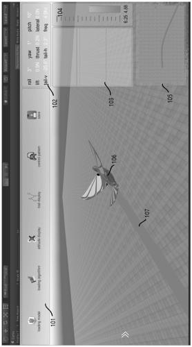
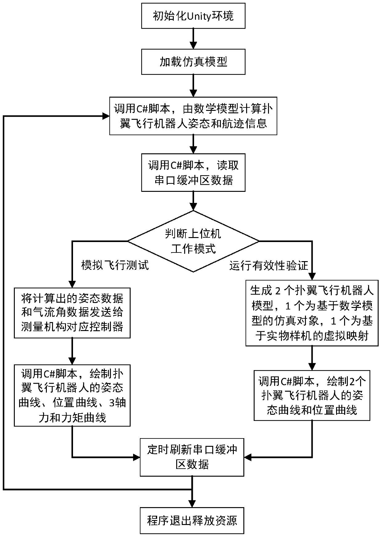
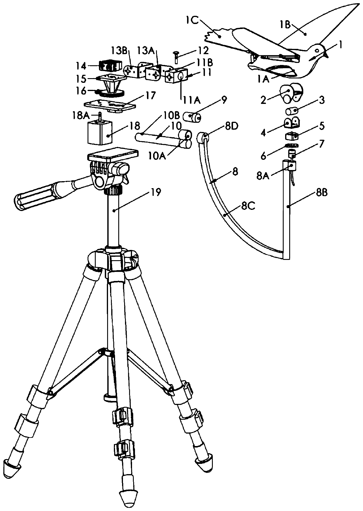
[0051] see Figure 1 to Figure 5 , the present embodiment provides a flight test system for a flapping-wing flying robot, the purpose of which is to be able to simulate the flight state of a flapping-wing flying robot and to facilitate the measurement of dynamic characteristics during flight. It is applicable to the field of flapping-wing flying robot technology. On the one hand, the prototype of the flapping-wing flying robot can be installed on the measuring mechanism, and the aerodynamic characteristics of the flapping-wing flying robot in the simulated flight state can be collected in combination with the ATI six-dimensional force sensor in the wind tunnel environment; On the one hand, in the outdoor flight test of the flapping-wing flying robot, the...
PUM
 Abstract
Description
Claims
Application Information
 - Generate Ideas
- Intellectual Property
- Life Sciences
- Materials
- Tech Scout
- Unparalleled Data Quality
- Higher Quality Content
- 60% Fewer Hallucinations
Browse by: Latest US Patents, China's latest patents, Technical Efficacy Thesaurus, Application Domain, Technology Topic, Popular Technical Reports.
© 2025 PatSnap. All rights reserved.Legal|Privacy policy|Modern Slavery Act Transparency Statement|Sitemap|About US| Contact US: help@patsnap.com