Stator for electrical machine, electrical machine and method for producing such stator

A stator and stator tooth technology, applied in the manufacture of motor generators, circuits, electrical components, etc.

Pending Publication Date: 2020-06-12
ROBERT BOSCH GMBH
View PDF2 Cites 0 Cited by
  • Summary
  • Abstract
  • Description
  • Claims
  • Application Information

AI Technical Summary

Problems solved by technology

After pressing several cutting-clamping elements into the receiving recess, there is a risk that the cutting-clamping elements move relative to the inserted wire during further assembly of the bearing cover and when contacting the electronics unit and thereby releasing its electrical contact

Method used


Image

  • Stator for electrical machine, electrical machine and method for producing such stator
  • Stator for electrical machine, electrical machine and method for producing such stator
  • Stator for electrical machine, electrical machine and method for producing such stator

Examples


Embodiment Construction

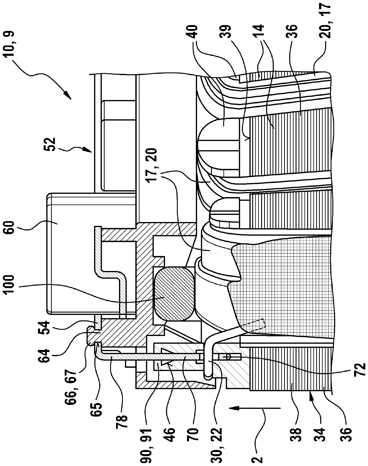
[0026] exist figure 1shows a stator 10 having a closed grounding ring 38 (Rückschlussring) in the circumferential direction 3 at which radial stator teeth 14 are formed to receive single-tooth coils wound with winding wire 22 17. In this embodiment, the stator teeth 14 are directed radially inwards, so that a rotor (not shown) which is driven by the stator 10 as an inner rotor can be supported within the stator teeth 14 . The stator 10 consists of individual metal laminations 36 which are stacked one above the other in the axial direction 2 and connected to form a common lamination pack. The metal laminations 36 are preferably stamped and formed such that the stator teeth 14 are formed in one piece with the grounding ring 38 . Arranged on the first axial end face 39 of the laminated core is a carrier plate 40 which preferably completely covers the end face 39 with an insulating material as an insulating mask. The carrier plate 40 is preferably designed as a plastic injectio...


PUM


Abstract

A stator (10), an electrical machine (9), and a method for producing a stator (10) with a stator base body (34) which has radial stator teeth (14) for receiving an electrical winding (20) are disclosed; the electrical winding (20) is connected to a separately manufactured connection plate (52) by means of an insulation displacement connection, receiving pockets (46) with an open edge (48) are formed on the stator main body (34) into which a winding wire (22) of the electrical winding (20 ) is inserted, insulation displacement elements (70) are formed on the connection plate (52) and are pressed into the receiving pockets (46), the insulation displacement elements (70) are attached on an open edge (48) in the receiving pocket (46) by means of plastic material forming (90).

Description

technical field [0001] The invention relates to a stator for an electric machine as well as to an electric machine and a method for producing such a stator according to the preambles of the independent claims. Background technique [0002] A stator for an electric machine is known from DE 10 2012 224 153 A1, in which insulating laminations, a carrier plate and a connection plate are arranged axially on a lamination stack. The stator is wound, for example, by means of a needle winding, wherein the individual partial coils are connected to one another by means of connecting wires on the outer periphery of the carrier plate. Here, the entire winding is wound in one piece by means of a single winding wire. Since the connecting lines between the individual coils are arranged axially overlapping one another, the overall axial height of the stator is relatively large. In addition, the costs for soldering the terminal block to the connecting wires are very high. [0003] DE 10 20...

Claims


Application Information

Patent Timeline
Patent Type & Authority Applications(China)
IPC IPC(8): H02K3/28H02K3/50H02K15/00
CPCH02K3/28H02K3/50H02K15/0068H01R4/2433H02K3/52H02K15/00
Inventor K.布劳恩M.福尔默T.德韦尔曼
Owner ROBERT BOSCH GMBH
Why Eureka
Try Eureka