Wounded warrior wheelchair driving wheel
A technology for driving wheels and wheelchairs, which is applied in the direction of wheels, hubs, patient chairs or special means of transportation, etc. It can solve the inconvenience of replacement, no impulsive starting, and avoid the user's upper body suddenly throwing back, and the brake does not rush forward. Immediately stop walking, inconvenient replacement and installation, etc., to achieve the effect of firm and stable installation, convenient and fast installation, and simplify the steps of replacing tires
- Summary
- Abstract
- Description
- Claims
- Application Information
AI Technical Summary
Problems solved by technology
Method used
Image
Examples
Embodiment 1
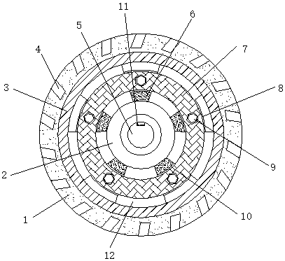
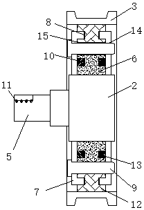
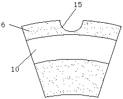
[0023] see Figure 1 to Figure 5 , the present invention provides a technical solution: a meritorious wheelchair driving wheel, including a hub 3, a connecting disc 2 is arranged on the inner side of the hub 3, a first splicing plate 6 is fixed on the surface of the connecting disc 2, and a second splicing plate 6 is fixed on the inner surface of the hub 3 Plate 12, through the design of the first splicing plate 6 and the second splicing plate 12, the two can be disassembled quickly, so that the hub 3 can be removed for quick replacement, avoiding the traditional disassembly and installation being too complicated and cumbersome, the first splicing plate 6 and The surface of the second splicing plate 12 is respectively provided with a first fixing groove 10 and a second fixing groove 8, and both ends of the first splicing plate 6 and the second splicing plate 12 are provided with mounting discs 7, through the designed mounting disc 7 and connecting ring 13. The two quickly snap...
Embodiment 2
[0025] see Figure 1 to Figure 5 , the present invention provides a technical solution: a meritorious wheelchair driving wheel, including a hub 3, a connecting disc 2 is arranged on the inner side of the hub 3, a first splicing plate 6 is fixed on the surface of the connecting disc 2, and a second splicing plate 6 is fixed on the inner surface of the hub 3 Plate 12, through the design of the first splicing plate 6 and the second splicing plate 12, the two can be disassembled quickly, so that the hub 3 can be removed for quick replacement, avoiding the traditional disassembly and installation being too complicated and cumbersome, the first splicing plate 6 and The surface of the second splicing plate 12 is respectively provided with a first fixing groove 10 and a second fixing groove 8, and both ends of the first splicing plate 6 and the second splicing plate 12 are provided with mounting discs 7, through the designed mounting disc 7 and connecting ring 13. The two quickly snap...
PUM
 Abstract
Description
Claims
Application Information
 - R&D
- Intellectual Property
- Life Sciences
- Materials
- Tech Scout
- Unparalleled Data Quality
- Higher Quality Content
- 60% Fewer Hallucinations
Browse by: Latest US Patents, China's latest patents, Technical Efficacy Thesaurus, Application Domain, Technology Topic, Popular Technical Reports.
© 2025 PatSnap. All rights reserved.Legal|Privacy policy|Modern Slavery Act Transparency Statement|Sitemap|About US| Contact US: help@patsnap.com


