Assembling device

An assembly device and workbench technology, which is applied to household components, household appliances, and other household appliances, can solve problems affecting production efficiency, achieve the effects of improving production efficiency, ensuring assembly accuracy and assembly efficiency, and improving assembly efficiency

Active Publication Date: 2020-06-16
WUXI FILIN ELECTRONICS CO LTD
View PDF6 Cites 0 Cited by
  • Summary
  • Abstract
  • Description
  • Claims
  • Application Information

AI Technical Summary

Problems solved by technology

[0002] At present, for motors with external rotor structure, such as DD (direct driver, direct drive) motors, during the manufacturing process, the magnetic tiles and the rotor need to be placed on the mold and injected into the rotor assembly to complete the fixing of the magnetic tiles and the rotor. However, due to the large number of magnetic tiles, as many as dozens of pieces, it is usually necessary to place the magnetic tiles one by one in the mold and then inject the rotor with the rotor. If one second is used to place a magnetic tile, it will take the time to produce a rotor assembly. Defined as a beat, the time for placing magnetic tiles accounts for more than one-third of the beat, seriously affecting production efficiency

Method used


Image

  • Assembling device
  • Assembling device
  • Assembling device

Examples


Embodiment 1

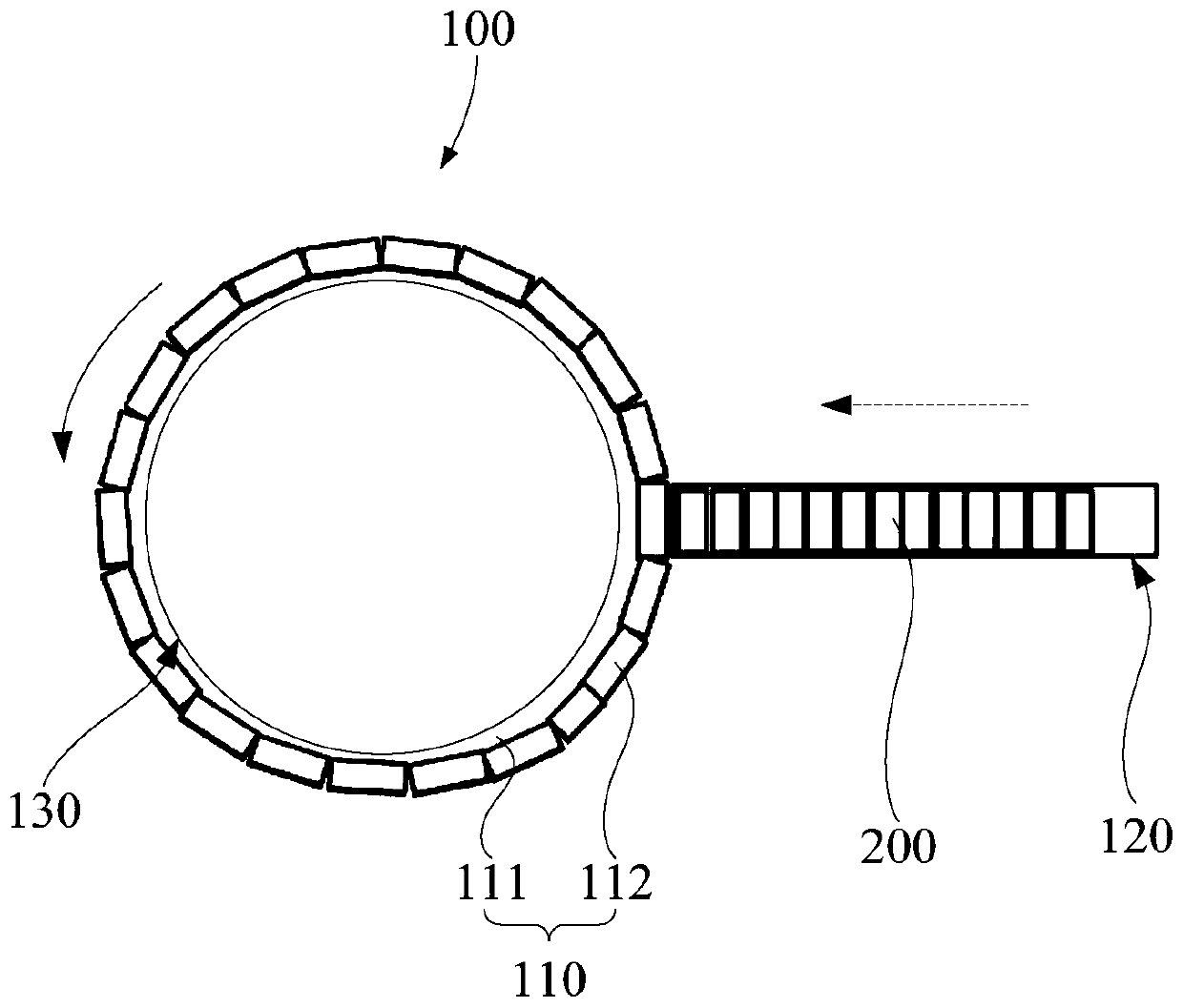
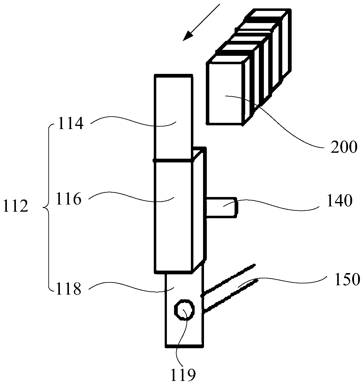
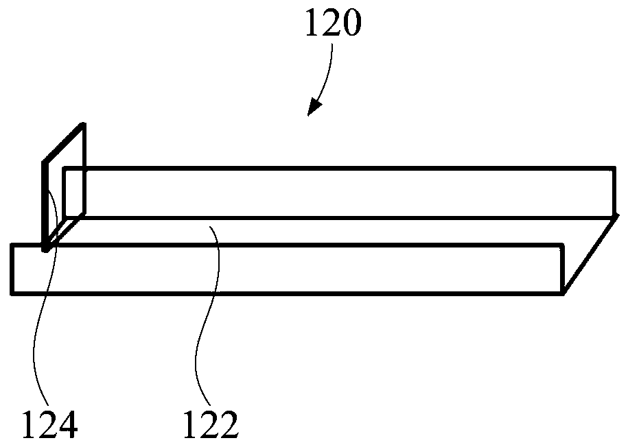
[0046] like Figure 1 to Figure 5 As shown, in one embodiment of the present invention, the assembly device 100 includes a workbench 110, a conveying part 120 located above the workbench 110, several positioning structures 112 arranged on the workbench 110 for positioning materials, and the positioning structures 112 are located on the workbench 110. Between the workbench 110 and the conveying part 120 , a fixing member 140 is disposed on the positioning structure 112 . The positioning structure 112 includes a positioning frame 116 and a first positioning portion 114 located above the positioning frame 116, wherein the first positioning portion 114 and the positioning frame 116 can be integrally formed or relatively fixed, and the position of the first positioning portion 114 corresponds to that of the conveying portion 120 The discharge end of the first positioning part 114 is configured so that the material 200 output by the conveying part 120 enters the positioning frame 11...

Embodiment 2

[0053] like Figure 1 to Figure 5 As shown, in one embodiment of the present invention, the assembly device 100 includes a workbench 110, a conveying part 120 arranged above the workbench 110, a mold 130 located below the workbench 110, and a mold 130 arranged between the workbench 110 and the conveying part 120. The positioning structure 112 between them, the fixing part 140 and the pushing part 150 arranged on the positioning structure 112 . The positioning structure 112 includes a positioning frame 116, a first positioning portion 114 positioned above the positioning frame 116, and a second positioning portion 118 positioned below the positioning frame 116, wherein the pusher 150 is arranged on the second positioning portion 118, based on the positioning frame 116 The material 200 inside is transported to the limiting portion 132 of the mold 130 , and the pusher 150 is configured to fix and position the material 200 inside the limiting portion 132 .

[0054] In this embodi...

Embodiment 3

[0058] like Figure 1 to Figure 5 As shown, on the basis of any one of the above-mentioned embodiment 1 or embodiment 2, the workbench 110 includes: a body, the body is configured as a cylinder, and the positioning structures 112 are distributed on the side of the cylinder along the circumference of the cylinder or the body is configured as a regular prism, and any positioning structure 112 is distributed on the side of any regular prism; wherein, the body is configured to be rotatable, and the axis of the body is parallel to the length direction of the positioning structure 112 .

[0059] In this example, if figure 1As shown, the workbench 110 includes a body. On the one hand, the body is configured as a cylinder, and the positioning structures 112 are distributed on the side of the cylinder or the outer edge of the body along the circumference of the cylinder. On the other hand, the body is a regular prism Each side of the regular prism is provided with a positioning struct...


PUM


Abstract

The invention provides an assembling device. The assembling device comprises a workbench and a conveying portion; the workbench is provided with positioning structures used for positioning materials;the conveying portion is used for conveying the materials and located on any side of the upper portion of the workbench, the positioning structures are located between the workbench and the conveyingportion, the upper ends of the positioning structures correspond to the discharging end of the conveying portion, and the positioning structures are provided with fixing parts used for fixing the materials. According to the assembling device, the positioning structures are arranged and provided with the fixing parts, one or more materials can be simultaneously fixed to the positioning structures and simultaneously conveyed to molds, therefore, the assembling time can be shortened, the production takt can be shortened, and the production efficiency can be improved.

Description

technical field [0001] The present invention relates to the technical field of assembly, in particular to an assembly device. Background technique [0002] At present, for motors with external rotor structure, such as DD (direct driver, direct drive) motors, during the manufacturing process, the magnetic tiles and the rotor need to be placed on the mold and injected into the rotor assembly to complete the fixing of the magnetic tiles and the rotor. However, due to the large number of magnetic tiles, as many as dozens of pieces, it is usually necessary to place the magnetic tiles one by one in the mold and then inject the rotor with the rotor. If one second is used to place a magnetic tile, it will take the time to produce a rotor assembly. Defined as a beat, the time for placing magnetic tiles accounts for more than one-third of the beat, which seriously affects production efficiency. Contents of the invention [0003] The present invention aims to solve at least one of t...

Claims


Application Information

Patent Timeline
Patent Type & Authority Applications(China)
IPC IPC(8): B29C45/14
CPCB29C45/14008B29L2031/7498
Inventor 陆桂荣张小文王永威刘建清
Owner WUXI FILIN ELECTRONICS CO LTD
Why Eureka
Try Eureka