
Air extraction system

An air extraction system and a technology of the air extraction system are applied in the field of air extraction systems and can solve problems such as lowering

Active Publication Date: 2022-02-01
SAURER SPINNING SOLUTIONS GMBH & CO KG
View PDF0 Cites 0 Cited by
  • Summary
  • Abstract
  • Description
  • Claims
  • Application Information

AI Technical Summary

Problems solved by technology

The negative pressure can for example be reduced so strongly that it is no longer possible to find the yarn end on the winding package surface

Method used


Image

  • Air extraction system
  • Air extraction system
  • Air extraction system

Examples


Embodiment Construction

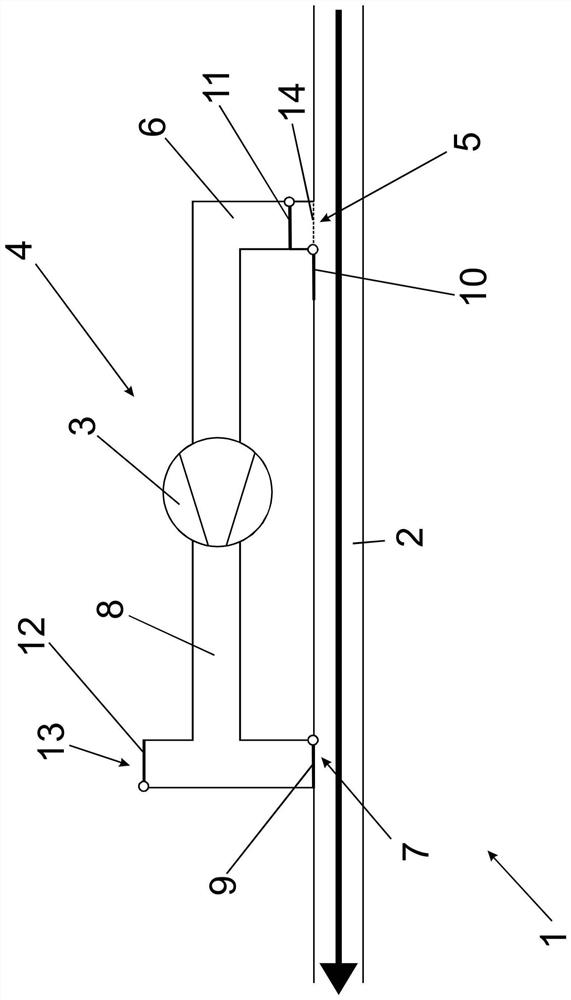
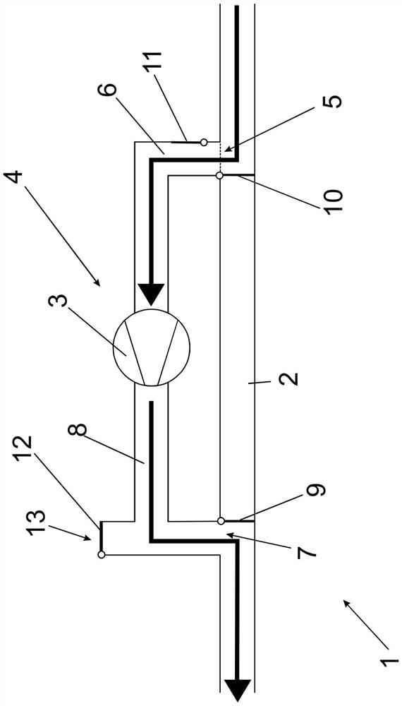
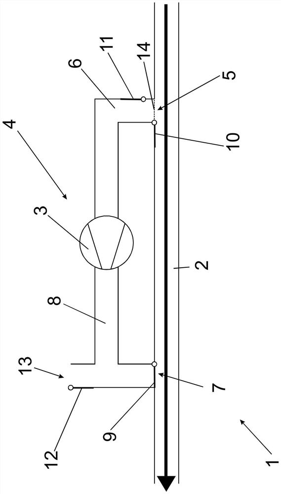
[0045] in such as Figure 1 to Figure 3 In the shown suction system 1, an additional suction system 4 is connected to the machine suction channel 2 via an inlet channel 6 and an outlet channel 8, whereby the stations of the textile machine not shown here are connected to supply all stations central suction channel. In order to connect the additional suction system 4 to the machine suction channel 2, an inlet 5 and an outlet 7 are provided at the machine suction channel 2, the inlet channel 6 or the outlet channel 8 being connected to the inlet or the outlet respectively. At their end opposite the inlet 5 or outlet 7 , the inlet channel 6 as well as the outlet channel 8 are connected to an additional source of negative pressure in the form of a fan 3 .

[0046] in such as figure 1 In normal operation shown, without switching on the additional suction system 4, the second closing element 10 is arranged in the open position for opening the suction channel 2 of the machine, and ...


PUM


Abstract

The invention relates to an air extraction system for providing a negative pressure at a work station of a textile machine in order to suck away air-conveyable waste and to suction and prepare a yarn end for its connection, which has a working position with the textile machine A suction channel connected in bit and a negative pressure source connected to the suction channel. In order to provide a suction system that ensures the correct operation of the textile machine stations even under high loads, it is provided that there is an additional suction system equipped with an additional vacuum source, which is thus connected to the suction channel , the additional negative pressure source can be connected in series with the negative pressure source.

Description

technical field [0001] The invention relates to an air extraction system for providing a negative pressure at a work station of a textile machine to suck away air-transportable waste and to suction and prepare the end of yarn for connection to the end of the yarn, having a connection with the work station of a textile machine The suction channel and the negative pressure source connected to the suction channel. The invention also relates to a textile machine with such an air extraction system. Background technique [0002] Textile machines, such as automatic winders or spinning machines, consist of a number of identical workstations which, in particular for their respective processes, at least sometimes require suction air, which is usually provided by one or more suction systems of the textile machine supply. Without limiting generality, and for the sake of simplicity, only a single extraction system is mentioned below within the scope of the present application. [0003...

Claims


Application Information

Patent Timeline
Patent Type & Authority Patents(China)
IPC IPC(8): B65H54/70D01H11/00
CPCB65H54/707D01H11/005B65H2701/31B65H54/88B65H67/08D01H15/00B65H54/702B65H69/063D01H11/006
Inventor T·福歇
Owner SAURER SPINNING SOLUTIONS GMBH & CO KG
Learn More