Water-vapor separation device with active drainage function

A water vapor separation and functional technology, applied in the field of medical devices, can solve the problems of complicated pipeline design, large number of booster pumps, and high negative pressure of vacuum pumps, and achieve the effects of increasing system reliability, sensitive action switching, and long working life.

Pending Publication Date: 2019-03-12
ZHONGHUI MEDICAL TECH (SHANGHAI) CO LTD
View PDF0 Cites 1 Cited by
  • Summary
  • Abstract
  • Description
  • Claims
  • Application Information

AI Technical Summary

Problems solved by technology

[0003] The current conventional equipment usually has the following defects: high vacuum pump negative pressure, large number of booster pumps, high volume and high power, high noise, complex pipeline design, lack of risk analysis and risk measures for single failure of pipelines, installation position between accessories There are strict location requirements, it is not easy to integrate small and portable, the design of the water collector is unreasonable, there is no water accumulation film, the water vapor separation efficiency is low, there is no active water drainage function, the drainage function is poor in adapting to the environment, and there is no constant value of dissolved oxygen. Based on ( Vacuum pressure value, vacuum pump flow rate, degassed water temperature,) vacuum pump speed regulation closed-loop control

Method used


Image

  • Water-vapor separation device with active drainage function
  • Water-vapor separation device with active drainage function
  • Water-vapor separation device with active drainage function

Examples


Embodiment Construction

[0031] The present invention will be described in detail below in conjunction with specific embodiments. The following examples will help those skilled in the art to further understand the present invention, but do not limit the present invention in any form. It should be noted that those skilled in the art can make several changes and improvements without departing from the concept of the present invention. These all belong to the protection scope of the present invention.

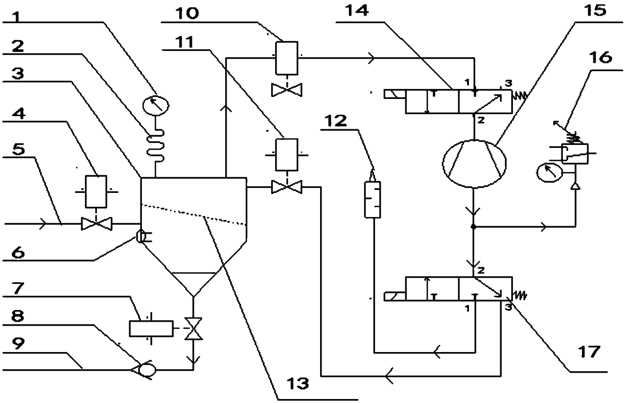
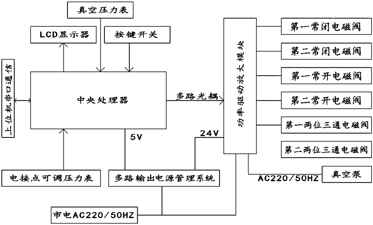
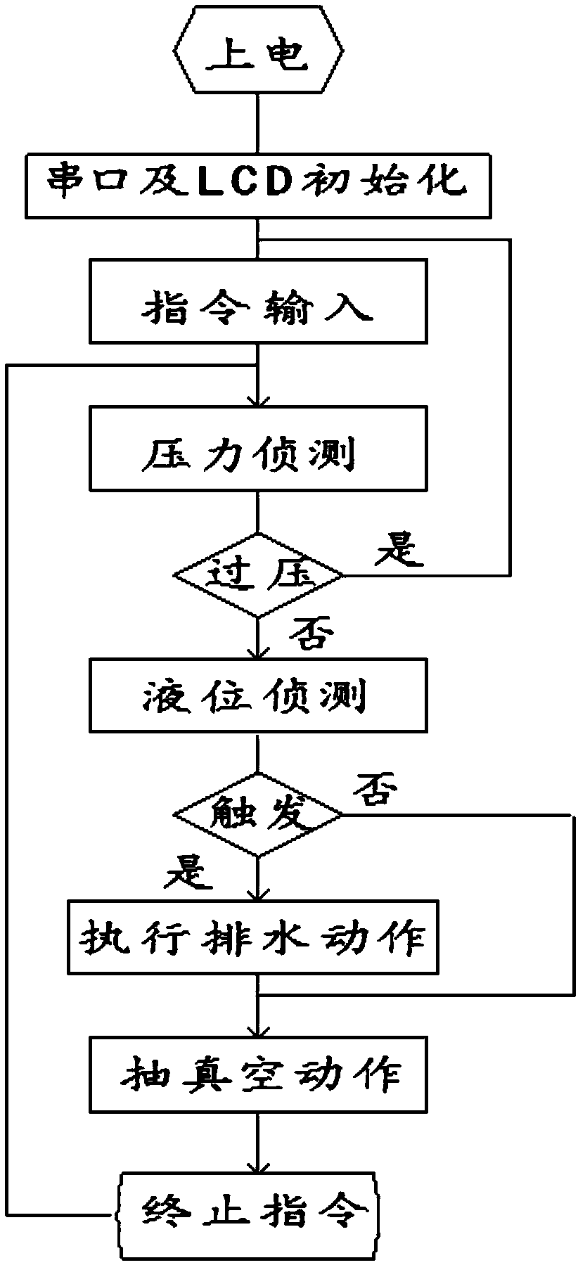
[0032] Such as Figure 1 ~ Figure 3 As shown, the water vapor separation device with active drainage function of the present invention includes: a vacuum water vapor separation container 3, a drainage vacuum pump, a pipeline connecting the drainage vacuum pump and the vacuum water vapor separation container 3, and an electrical control system.

[0033] The vacuum water vapor separation container 3 includes a liquid level trigger switch 6, a water accumulation film 13, a first normally open electromagnet...


PUM


Abstract

The invention provides a water-vapor separation device with an active drainage function. The water-vapor separation device comprises a vacuum water-vapor separation vessel, wherein a water accumulation membrane is arranged in the vacuum water-vapor separation vessel; one end of a first vacuum tube is communicated with the bottom of the vacuum water-vapor separation vessel, and the other end of thefirst vacuum tube is communicated with the atmosphere; one end of a second vacuum tube is communicated with the lateral part of the vacuum water-vapor separation vessel, and the other end of the second vacuum tube is communicated with a hollow fiber tube; an air inlet end of a second normally closed solenoid valve is communicated with the top of the vacuum water-vapor separation vessel; a first port of a first two-position three-way solenoid valve is communicated with an air outlet end of the second normally closed solenoid valve; an air inlet end of a vacuum pump is communicated with a second port of the first two-position three-way solenoid valve; a second port of a second two-position three-way solenoid valve is communicated with an air outlet end of the vacuum pump; an air inlet end of a second normally open solenoid valve is communicated with a third port of the second two-position three-way solenoid valve; and an air outlet end of the second normally open solenoid valve is communicated with the top of the vacuum water-vapor separation vessel. The water-vapor separation device provided by the invention solves the problems that the accumulated water is quickly discharged and water and vapor are not separated thoroughly.

Description

technical field [0001] The invention belongs to the field of medical equipment, in particular to a water vapor separation device with an active drainage function. Background technique [0002] In the ultrasonic tumor treatment system, the ultrasonic wave emitted by the phased array ultrasonic transducer must pass through the medium water to be coupled into the tissue and focus. Because the degassed water has good sound permeability and is cheap, degassed water is often used as the medium water. When the treatment head When working with high strength and high power, the degassing completeness of the degassed water is affected by the water temperature in the hollow fiber degassing membrane, the vacuum pressure value of the vacuum pump and the vacuum flow rate of the vacuum pump, and the temperature of the medium water in the hollow fiber membrane rises during the treatment process. The dissolved oxygen content in the degassed water will decrease. Insufficient vacuum will lead ...

Claims


Application Information

Patent Timeline
Patent Type & Authority Applications(China)
IPC IPC(8): C02F1/20A61N7/00
CPCC02F1/20A61N7/00
Inventor 彭良银王文波
Owner ZHONGHUI MEDICAL TECH (SHANGHAI) CO LTD
Why Eureka
Try Eureka